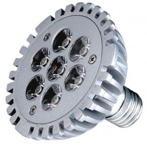
20 actual 80 years, the exact size of the small low-power quartz metal halide lamp to get a breakthrough in both design and production. Meanwhile, with people’s lives and exchanges between the quickening pace of completion of the highway, requires continuous improvement of the car at night driving safety, which requires headlamps visual construct, so the world began with a small power xenon metal halide lamps instead of the light of conventional halogen headlamp. Several atmospheric high-pressure xenon filled lamp(led lights) as a startup gas to meet the instantaneous luminous requirements of the automobile headlamp. At present, high-intensity car headlights electronic ballast system is one of the focus, but the electronic ballast design complexity, expensive and bulky, is only applicable to high-end cars and other applications. Obviously, if we reduce the size and cost, its demand will substantially increase, and therefore has a very good application prospects.
In this paper, analog control, auto headlamps electronic ballasts, the analog circuit to control the car headlights from the start to the stability control tasks, including constant power, ignition control.
(2) the basic circuit structure
In order to meet the different requirements of the lights in the startup and steady state, generally used in car headlights with electronic ballast circuit structure contains some of the features .
(1) DC / DC boost circuit due to the current automotive power for 12V lead acid batteries, lamp steady-state voltage of about 85V, and therefore must go through a step-up circuit battery voltage increased.
(2) high-voltage start circuit need high-voltage pulse to the lamp breakdown discharge and therefore require high-voltage start circuit lamp is lit. The start circuit can be taken one or two step-up manner to generate more high-voltage pulse of at least 23kV.
(3) DC / AC conversion circuit DC boost circuit output to DC, you must use the inverter circuit, DC into AC square wave current of the lamp required. The inverter circuit is generally a full-bridge inverter. The full-bridge inverter circuit to provide low-frequency AC square wave current to the lamp, in order to avoid the occurrence of acoustic resonance.
(4) when the lamp start of the drive and protection circuit to control start-up circuit. The lamp is lit, the detection voltage and short circuit occurred. Through the detection of lamp voltage and lamp current signal to control drive and protection circuits, lamp work stably.
Boost converter to meet the normal work requirements in light, we must also consider the no-load output voltage capability of the circuit. The no-load output voltage is decided by the circuit design of ignior circuit and take over.
(1) in the circuit topology, Boost circuit is the simplest. When the switch S in a large duty cycle, you can get a high output voltage. However, in this kind of work conditions, the output diode existence of the reverse recovery problem, the switch voltage and current stress, loss.
(2) For a forward converter, although it can achieve the purpose of the boost, but its no-load output voltage capability than the flyback converter. A forward converter transformer does not need to store energy, so the size of the transformer core can be very small, but must increase the number of turns of the secondary winding to the output voltage of 400V, and therefore require a large window area. Excessive secondary winding will lead to the increase of transformer copper loss and improve efficiency.
(3) Flyback converter as a DC / DC level topology by additional ignition winding, reducing the switch stress of the DC / DC level, increasing the reliability of the circuit; if the digital control circuit can work at the critical continuous state can achieve more, thereby reducing the circuit cost.
In addition, the main circuit topology of the car headlights electronic ballast comprehensive consideration of these methods is generally used as shown in Figure 2 Flyback converter and low-frequency full-bridge inverter circuit as the main circuit topology.

