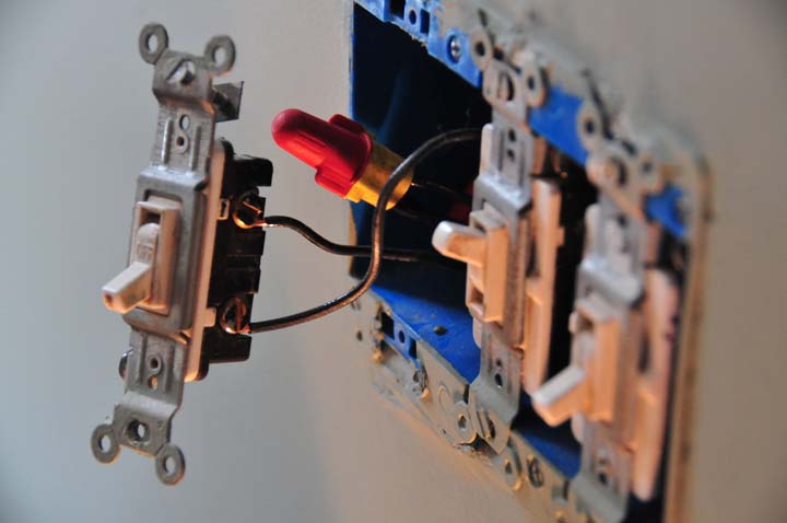
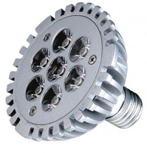
remote controlled spotlights and led advantage

As an emerging technology, semiconductor lighting industry is still in a stage of rapid development, scientific and technological progress we are delighted, but we also realize that both the technical aspects or the rules and regulations of the industry, compared with conventional light sources are not mature, not a sound. To really achieve with LED instead of traditional light sources, there is still a long way to go, there are many technical problems need to be addressed.

remote controlled spotlights and led advantage

3, LED technical problems

In theory LED luminous efficacy of up to 200lm / W, while the existing white LED only 70lm / W or so, and energy-saving fluorescent lamps still lags far behind; and its price compared with conventional light sources, there are big disadvantages (see right).

And therefore how quickly the advantages of the LED lights really play out has become practitioners must face technical problems. To really carve out a new semiconductor lighting era, we need to efforts to overcome technical problems as well as from the following aspects to further standardize the semiconductor lighting market.

3.1, the LED chip

The chip is the core of the LED, the internal quantum efficiency of direct influence on the luminous efficacy of LED, non-radiative recombination rate determines the size of the chip heat production. It can be said that the only manufacture LED chips with good quality, it may have a superior performance of the LED light source.

In order to maximize the internal quantum efficiency, and reduce non-radiative recombination rate, mainly from two aspects to improve the quality of silicon, is to choose the chip structure and defect density of the control chip.

LED chip structure of a single heterostructure, double heterostructure and quantum well structure, its luminous efficiency has great impact. Currently the most widely used and most efficient chip architecture for multi-quantum well structure (Multi-Quantum Well Structure,).

For the LED, the wafer and the substrate lattice constant and thermal expansion coefficient matching, wafer preparation process will directly affect the density of lattice defects. These defects may, under certain conditions, especially for Ⅲ – nitrogen light may be beneficial, but in most cases, because of the presence of these defects, will shorten the continuous working life of the chip, reducing the carrier density and thus reduce the light-emitting output, and may become non-radiative recombination centers.

How to choose a reasonable chip structure, understanding of lattice defects in the light-emitting LED chip mechanism to better control the generation of adverse defects.

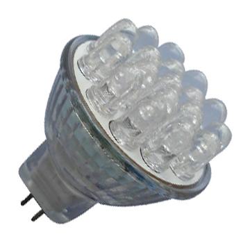
replace led bulb and current drivers

White LED usually has four different driver circuit: (a) the voltage source and ballast resistors, (b) current source and ballast resistors, (c) multiple current sources, (d) a current source driver series led lights.

replace led bulb and current drivers
Each white LED forward voltage (Vf) the impact of the current regulation accuracy, depending on the structure of regulation circuit: (a) voltage source and ballast resistors, (b) current source and ballast resistors, (c) multiple current source or a current source connected in series LED. 6 LED Vf curve (three from vendor A and B) are shown in the figure, the regulator output load curve and the LED’s Vf curve of intersection is the regulation of the operating point.

Circuits use a voltage regulator ballast resistors to control the LED current, the advantage of this structure there is considerable room to select the voltage source between the regulator and LED only need one connection endpoint; drawback is low efficiency, which is the main town resistor loss caused, in addition, its control of the LED forward current is not very accurate. Figure 5a test curve can be seen six different LED current range: 14.2mA to 18.4mA average luminance than the manufacturers provided by vendor A LED B is higher, the work of currents higher than 2mA.

The MAX1910 is this structure, this circuit can drive the same vendor products in the same batch to obtain good results. In the above circuit to provide the same current conditions, you can reduce the ballast resistors to reduce power consumption by half.Figure 5b shows the range of six different LED drive current: 15.4mA to 19.6mA, the LED current changes provided by the manufacturer A smaller average from vendor A and vendor B LED control current is the same: 17.5mA. The defects of this structure is the ballast resistor power consumption is still large, and the LED current matching is not very good. However, this circuit a good compromise between performance and ease of circuit.

The current regulation accuracy and matching of the individual current regulator. The MAX1570 uses a current source structure, the current accuracy of 2%, matching up to 0.3%. Low dropout current regulator, you can get higher efficiency. Figure 5c shows that all tested six white LED flood lights current is maintained at a stable 17.5mA, eliminating the need for ballast resistors, which can effectively save board space, but four terminals are required between the regulator and LED. This circuit can provide a high level of performance is based on the competition program of the inductor structure.

Lower feedback threshold to further reduce the sense resistor’s power consumption, because the LEDs are arranged in series connection, and under any working conditions are able to make the LED brightness is consistent. The current accuracy depends on the accuracy of the regulator’s feedback threshold from the LED’s forward voltage variations.The MAX1848 and MAX1561 are two typical examples of this current regulator circuit, conversion efficiency (PLED / PIN) can reach 87% (3 series LED) or 84% (6 LEDs in series). Another advantage of this circuit is between the regulator and LED only requires two connection endpoints, provide some flexibility for the user’s design. However, because the circuit uses inductance, a larger size, higher cost compared with the above-mentioned program, EMI radiation is also larger.


replacement led car bulbs and testing method

LED lighting technology standards focus on solving the problem of product characteristics and test methods, the LED is the most important performance indicators is the optical properties and electrical characteristics. The optical properties of luminous flux, light distribution, brightness, spectral distribution, chromaticity coordinates, color rendering index.

LEDs used in lighting fixtures, both for the general in the optical light source similar to the common particularity and its products: LED is a directional light emitting devices; the luminous body is very small, can be approximated point light source; light-emitting affected by environmental and processing process impact.

replacement led car bulbs and testing method

LED lights decay characteristics of the measurement cycle is very long (tens of thousands or even tens of hours). LED illumination in addition to the optical properties are involved, as well as its electrical attachment properties (including energy-saving electrical attachment), mechanical properties, temperature characteristics, and utensils, and security features.

Therefore consider the problem of testing methods in the standard setting process to focus on

The first is to choose the adoption and development of LED characteristics of test equipment, to create a test system. Including: LED optical test systems, temperature monitoring and test systems, electrical testing, environmental testing, durability, reliability test system. The main test system should adopt international advanced tools, test methods should be able to approach international advanced level.

Through cooperation and exchange with foreign laboratories, our LED detection technology and international developments, so that the standard can objectively reflect the technical level of China’s LED lighting compatible with the rapid development of China’s LED lighting, but also consistent with international standards
Further promote the development of LED panel technology.

LED lighting standards for a series of standards

The series of standards in the basis of the standard (or standards) single-tube LED lighting standard and test method standards in LED lighting standards on the basis of this system. LED standards must first be resolved to the characteristics of the LED light source in the lighting requirements, determine the technical requirements of the LED light source, the main technical characteristics and technical parameters of the LED and the LED detection to find, to determine the technical level of China’s LED lighting and related technical specifications and technical requirements.

Quickly due to the development of LED lighting technology, LED lighting development of standards with the development of technology and market needs to adapt. Standardization bodies, inspection bodies, lighting LED research department, production enterprises and application units should complement each other and work together to establish a set to meet China’s national conditions, advanced technology and LED lighting of the national standards.

replacement led flashlight bulbs and power solution

As large numbers of solid state light source, light-emitting diode (LED lights), incandescent increasingly lonely. In the past few years, LED technology has been tremendous progress, making LED cooling, packaging and process technology advances have higher brightness, higher efficiency, longer life and lower cost.

However, the efficiency of energy conversion, thermal management, and production costs, LED still has further room for improvement. For example, LED efficiency has been greatly improved. Many improvements in the LED from the better chip to produce light, and there are better ways to get light from the chip and its package. Similarly, 20mA white LED prices have significantly reduced this LED has just launched, lots of share offer for $ 1. At present, 20mA white LED may be approved purchase price of less than 30 cents to buy.

replacement led flashlight bulbs and power solution

LED lighting applications needs analysis

Of course, all these advances not only promoted the LED as the lighting of use in different applications, but also stimulated the demand for LED driver IC. To understand the design and manufacture of LED driver IC to face obstacles, it is necessary to understand the white LED light-emitting What are the conditions. White LED with a constant current source driver, so that the white points of light will not change (that is, the brightness must be consistent). In addition, since the white LED is a diode, then it must overcome its internal forward voltage drop (Vf). Vf with the white LED current value will change with changes in temperature. Under normal circumstances, within the entire operating temperature range, 20mA white LED Vf in the range from 2.5V to 3.9V. Most applications, multiple white LEDs, these LED may also be configured in parallel, in series or series-parallel hybrid forms. This means that the white LED driver IC must be able to provide for the specific configuration of multiple LED current and voltage and the voltage converter topology used in this IC must also meet the input voltage range and output voltage and current requirements.

The biggest driving force of the LED common applications include automotive and aircraft instrument panel display and instructions, traffic lights, cell phones, flat panel display backlight, miners lamps, buildings and outdoor large-scale stadium lighting, and the current and future years, the LED market growth from the flat panel display backlighting requirements. These displays use LCD screen for TV sets, navigation systems, portable media players, digital billboards, and computer monitors. However, the LED facing the challenges of thermal management technology. Although LED Unlike other light sources, as so much heat radiation, but depending on the output power, some LED may require a suitable heat sink, so that light output will not reduce the life expectancy is not shortened. For example, the power light output for the the 25lm high brightness LED is generally consumed more than 1W. This means that the white LED driver IC with high efficiency must be converted so that it can not become the main cause of heat problems. In addition, in many cases there are space-constrained problem, the LED driver solutions to small footprint, and small size.

Mobile phone, for example, most cell phones today have built-in digital camera that can shoot high-resolution photos and videos. Camera improved performance has also led to the demand for high-power white light, the camera indoors or in dim environments need to use this light, the white LED main light source for a camera phone. Because the white LED has a wide range of modern cell phone designers want the features: small size, high light output, can provide the “Flash” and “video” object of continuous illumination. Has been specifically developed for the integrated camera lighting the high output power LED.

Although the use of high-power LED visible light is very simple, but if the wrong has been designed to improve, to form a high-performance power supply and current control solution is very difficult. Linear Technology’s LTC3454 is a new product designed specifically for high-current camera lighting applications to improve power conversion efficiency and accuracy, and optimize the control of LED current.

replacement led lamps and life span

LED industry in the past in order to profit fully white LED beam, once the development of large-size LED chips trying to take this way to achieve the desired goals, but actually exert power white LED lights continuous beam but will decline more than 1W above, the luminous efficiency is relatively lower 2030 %, in other words white LED brightness several times larger than traditional LED power consumption characteristics beyond the fluorescent lights, you must first overcome the following four topics, including inhibition of the temperature rise to ensure that the service life, improve light-emitting efficiency, as well as luminescent properties equalization.

replacement led lamps and life span
Is to reduce the package thermal impedance on temperature rise problems; maintain LED life is to improve the chip shape, a small chip; specific methods to improve the chip architecture, small chip to improve the LED luminous efficiency; As for the light-emitting characteristics of uniform of specific methods of improvement of the LED package, and these methods have gradually been developed.

The package thermal problem is the fundamental method

It will cause the package thermal impedance is drastically reduced to below 10K / W due to the increased power, foreign companies have developed high-temperature white LED an attempt to improve the problem, However, in practice the high-power LED heat than low-power LED high number of more than ten times the luminous efficiency and temperature rise will be declined substantially, even if the packaging technology allows high-calorie, but the LED chip junction temperature there is likely to exceed the allowable value
And finally the industry has finally realized that the heat dissipation problem is the fundamental method to solve the package.

LED life, for example, to switch to the silicon packaging materials and ceramic packaging materials, make the life of the LED’s to improve a number of white LED light spectrum contains wavelengths below 450nm short wave length light, traditional epoxy encapsulated materials can easily be short-wavelength light damage, high-power white LED light to accelerate the degradation of packaging materials, continuous lighting of less than one million hours, according to the test results of the industry, high-power white LED brightness has been reduced by more than half simply can not meet the basic requirements for lighting long life.

Remove, not easy from the large chip, can achieve the same level with the low-power white LED chip package structure for LED luminous efficiency improvement, mainly due to the current density increased by more than 2 times, not only light, a result, it will cause the luminous efficiency the dilemma of not as good as low-power white LED, improving the electrode structure of the chip, in theory, the light extraction issues can be resolved.

try to reduce the thermal resistance to improve the heat dissipation problem

For light-emitting characteristics of uniformity, is generally believed that as long as the production technology to improve the uniformity and phosphor white LED phosphor materials concentration should be able to overcome this trouble. As described above to improve exert power at the same time, it is necessary to reduce the thermal impedance to improve the heat dissipation problem, the specific contents are: to reduce the chip to the package thermal impedance, inhibiting the thermal impedance of the package to the printed circuit board, improve the smoothness of chip cooling.

In order to reduce the thermal resistance, many foreign LED manufacturers LED chip set heat sink made of copper and ceramic materials (heat sink) surface, and then using the welding heat to the printed circuit board with a wire connected to the use of the cooling fan forced air cooling fins, according to German OSRAM Opto Semiconductors Gmb experimental results confirmed the above-mentioned structure of the LED chip to the thermal impedance of the welding point can reduce the 9K / W is about 1/6 of the traditional LED, the LED package to impose 2W of power, the LED chip junction temperature than welding point high 18K, even if the printed circuit board temperature rises to 500C junction temperature at most only about 700C; previous thermal impedance contrast lower, then the LED chip junction temperature will The temperature of printed circuit board, this way necessary to try to reduce the temperature of the LED chip, in other words reduce the thermal impedance of the LED chip to the welding point, can effectively reduce the burden of the LED chip cooling operation. On the other hand the white LED is able to inhibit the thermal impedance of the structure, if the heat conduction from the package to the printed circuit board, LED temperature rise results luminous efficiency will be dramatically decreased by Matsushita Electric Works to develop printed circuit board and package integration technologies, the 1mm square blue LED flip chip packaged in a ceramic substrate, and then paste then the ceramic substrate in the surface of copper printed circuit board, according to Matsushita said contains a printed circuit board module as a whole, including the thermal impedance is about 15K / W or so.

replacement led light bulbs and power switch

High-power LED lights are increasingly being used in a variety of areas, including automotive lighting, camera phone flash, stage lighting, workplace lighting, landscape lighting, flash, bicycle lights and cars running lights. This article will discuss the various technical problems and distribution switches in LED applications.

At present, the limiting distribution switch is one of the best choice for designers used to drive the LED. This is because the distribution switch operation, and better able to control the distribution system a variety of load. Its function is simple: in the state of the switch is turned on, allowing current to flow to the load, the switch turned off, preventing current flow to the load.

replacement led light bulbs and power switch

This switch also has a limiting function, that is, when the switch is turned on, the maximum current load is equal to the current limit set by the switch. This limit function is necessary to design a constant current LED driver.

Why designer so need to constant-current LED drive? LED light intensity is constant because the flow through the LED current is constant, even in the case of flow through the LED voltage change will not change. This is necessary for the application of the requirements of a stable light intensity.

When the switch is open, the LED will try to absorb as current as possible, but due to limitations of the switch, only 350mA. Therefore, as long as the switch is open, and switch the input voltage (Vin) within the range of 2.5V to 5.5V, the flow through the LED current can be always maintained in the 350mA.

With current-limiting switch, the LED current limit will be able to be adjusted between 200 mA to 2 A by changing the resistor values ​​in Rset. A limiting value range so wide, you can apply to a variety of high-power LED, and can be used for a variety of applications.

This IC with Cslew pin capacitor between Cslew and Vin to connect through it. Cslew capacitors can be used to extend the opening time of the LED. At the same time, it comes with a built-load discharge transistor (P-channel FET). When the switch is off, the FET will release the output current.

In some applications, the need to gradually open and close the LEDs, so the audience will not be sudden change in light conditions and transient blindness. Figure 3 shows one can arbitrarily set the opening time and closing time of the program.

Here, open the input and Vin are related (Figure 3 display Cslew pin) pin Ilimit issued a 5 V signal to open and close the control.

To calculate the limiting value of the circuit in Figure 3, the required sum of 0.5 kΩ and 0.2 kΩ (3.33 kΩ and 0.212 kΩ resistor in the equivalent resistance), obtained 0.7 kΩ. In this case, the limiting value is 245/0.7 kΩ = 350 mA. In addition, through a 680 μF capacitor values, opening and closing time is set at 300 ms. This time is calculated: 2.2 x R x C = 2.2 x 0.2 kΩ x 680 μF = 300 ms.

MIC2007 can switch to turn on and adjust the current limit after the LED is lit. By changing the current limit, it can dynamically adjust the LED light intensity. Shown in Figure 5, there are four resistors are connected to Ilimit pin.

If 4 of the resistor value, the LED light intensity can have four different levels. Several resistors connected to Ilimit pin, you can get several levels of the LED light intensity.

If the resistor’s value, by using different combinations of resistors to adjust the intensity of LED light. For example, if the resistance value of R, R / 2, the R / 4, the R / 8 and R/16 5 resistors have been used, the combination of R, the R / 2 and R / 4 three resistors LED The light intensity is even lower, while the combination of R / R / 8 R/16 three resistors, LED’s light intensity is higher.

Micrel’s MIC2000 series limiting distribution switch allows a maximum of 2A current flows to load such a large current is sufficient for most of the load in the system. Limiting distribution switches to many designers are using the high power LED load to meet the growing demands of a variety of lighting applications in the market today.

residential led light bulbs and MH lights design

Metal halide lamp is a third generation of electric light, because of its high luminous efficiency, long life such as led lights, play an increasingly important role in the green lighting. As an energy-saving lighting appliances, electronic ballasts, has become one of the key elements of the implementation of green lighting. Compared with the traditional magnetic ballast, electronic ballast volume and weight are greatly reduced, to improve network power quality, improved lighting quality. However, the universal application on the market today is the inductance ballast, mainly due to the simple structure, high reliability, and inexpensive. Therefore, the development of metal halide electronic ballasts higher requirements must be met to reliably start metal halide lamp; provide constant rated power; the need to eliminate the acoustic resonance phenomenon; protection function. In this paper, design for indoor lighting, small power metal halide lamp electronic ballast topology, to study the control strategy.

residential led light bulbs and MH lights design

Start-up phase and steady-state phases using the half-bridge parallel load resonant (ParallEL Load Resonant, referred to as PLR) circuit and the half bridge dual Buck circuit. Before the start of the metal halide lamp, the arc tube filled with inert gas is not ionizing, light in a high impedance state can be approximately considered to be open. In the startup phase in Figure 1 Relay disconnect switch VQ1 and VQ2 complementary high-frequency drive signal. Figure 2 shows the PLR ​​circuit. Parallel resonant capacitor Cp to generate high voltage and resonant inductor L (L1 and L2) in the high-frequency AC voltage, driven by resonance of the Cp at both ends.

From high frequency to low frequency, fc the closer fz, the greater the amplitude of Cp on the resonant voltage ur. The input voltage of the PLR ​​circuit is rich in odd harmonics of the square wave voltage. Fz, the fundamental frequency of the square wave voltage is higher than the circuit is designed only to consider the fundamental and ignore the impact of high harmonics; fz, if the fundamental frequency of square wave voltage is lower than the circuit must be considered high harmonic frequency, harmonic resonance may become a major part of ur. This article 3 times ur resonance, effectively reduces the series inductance in the startup current, improve the reliability of the power circuit.

Furthermore, using the right side of the resonant peak from high to low slip frequency, the resonant circuit can be realized in the emotional area, VQ1 VQ2 the zero-voltage, reducing MOSFET switching losses. Due to the discrete nature of the parameters, the design of the resonant peak (Figure 3, curve 2) may be to the left (Figure 3, curve 3) or right (Figure 3, curve 1) offset. If you rely on to set slip frequency cut-off point to control the boot process, when the resonant peak is shifted to the left, to the slip frequency cut-off point, ur may still be unable to lamp is lit; when the resonant peak is shifted to the right, the boot process may be slippery over the resonant peak, resulting in excessive ur damage to the power switch. Therefore, by setting start voltage ug limit amplitude control the slip frequency cut-off point. When the slip frequency of the high-pressure reaches the voltage limit amplitude, high pressure, automatic stop sliding frequency.

After the lamp is lit, the light from high-impedance characteristics into the nature of the low resistance. Until the lamp arc stability, lamp power reaches the set value, in Figure 1 Relay is closed, the drive signal into a low frequency square wave signal with frequency modulation. In this case, the circuit structure and operating mode has the obvious symmetry, Buck circuit characteristics in the low-frequency switching cycle, Figure 4 shows the structure of the half bridge dual Buck circuit. Lamp voltage u0 and lamp current io are low frequency square wave signal, can effectively inhibit the light acoustic resonance phenomenon. Because the square wave uo and io resistive when the volt-ampere characteristics of low power metal halide lamp, alternating positive and negative changes in lamp power AC component, which can not stimulate the resonator.


Design of electronic ballasts FREESCALE 8-bit microcontroller for the control of the core, the lamp power closed-loop control and protection functions by detecting the lamp terminal voltage uc and dc bus current, open circuit, short circuit and abnormal state when the light side ballast automatic protection. Figure 5 shows the control block diagram. Starts, the high-frequency square-wave signal control circuits output complementary control VQ1 off VQ2 the frequency from high to low slide, uc gradually increased, the limit set uc to control the slip frequency cut-off point. When when the uc suddenly landed, and to judge the value below the set, the ionized gas in the lamp arc tube, into a single frequency transient transition; when the lamp power reaches the set value, description of the lamp has been lit, to meet the switching conditions; Relay closed circuit from parallel load resonant switch to the half bridge dual Buck circuit structure, the control circuit output with high-frequency modulation of low frequency square wave signal, and the closed-loop control of steady state power. Half Bridge Dual Buck inputs of the circuit is of 400V Ubus, sampling will be able to link current approximate control lamp power. During the transition or steady state control stage light side open or short, you can automatically block the power circuit output, enter the state of the delay protection.

residential led light fixtures and car ballast

20 actual 80 years, the exact size of the small low-power quartz metal halide lamp to get a breakthrough in both design and production. Meanwhile, with people’s lives and exchanges between the quickening pace of completion of the highway, requires continuous improvement of the car at night driving safety, which requires headlamps visual construct, so the world began with a small power xenon metal halide lamps instead of the light of conventional halogen headlamp. Several atmospheric high-pressure xenon filled lamp(led lights) as a startup gas to meet the instantaneous luminous requirements of the automobile headlamp. At present, high-intensity car headlights electronic ballast system is one of the focus, but the electronic ballast design complexity, expensive and bulky, is only applicable to high-end cars and other applications. Obviously, if we reduce the size and cost, its demand will substantially increase, and therefore has a very good application prospects.

In this paper, analog control, auto headlamps electronic ballasts, the analog circuit to control the car headlights from the start to the stability control tasks, including constant power, ignition control.


(2) the basic circuit structure

In order to meet the different requirements of the lights in the startup and steady state, generally used in car headlights with electronic ballast circuit structure contains some of the features .

(1) DC / DC boost circuit due to the current automotive power for 12V lead acid batteries, lamp steady-state voltage of about 85V, and therefore must go through a step-up circuit battery voltage increased.

(2) high-voltage start circuit need high-voltage pulse to the lamp breakdown discharge and therefore require high-voltage start circuit lamp is lit. The start circuit can be taken one or two step-up manner to generate more high-voltage pulse of at least 23kV.

(3) DC / AC conversion circuit DC boost circuit output to DC, you must use the inverter circuit, DC into AC square wave current of the lamp required. The inverter circuit is generally a full-bridge inverter. The full-bridge inverter circuit to provide low-frequency AC square wave current to the lamp, in order to avoid the occurrence of acoustic resonance.

(4) when the lamp start of the drive and protection circuit to control start-up circuit. The lamp is lit, the detection voltage and short circuit occurred. Through the detection of lamp voltage and lamp current signal to control drive and protection circuits, lamp work stably.


residential led light fixtures and car ballast

Boost converter to meet the normal work requirements in light, we must also consider the no-load output voltage capability of the circuit. The no-load output voltage is decided by the circuit design of ignior circuit and take over.

(1) in the circuit topology, Boost circuit is the simplest. When the switch S in a large duty cycle, you can get a high output voltage. However, in this kind of work conditions, the output diode existence of the reverse recovery problem, the switch voltage and current stress, loss.

(2) For a forward converter, although it can achieve the purpose of the boost, but its no-load output voltage capability than the flyback converter. A forward converter transformer does not need to store energy, so the size of the transformer core can be very small, but must increase the number of turns of the secondary winding to the output voltage of 400V, and therefore require a large window area. Excessive secondary winding will lead to the increase of transformer copper loss and improve efficiency.

(3) Flyback converter as a DC / DC level topology by additional ignition winding, reducing the switch stress of the DC / DC level, increasing the reliability of the circuit; if the digital control circuit can work at the critical continuous state can achieve more, thereby reducing the circuit cost.


In addition, the main circuit topology of the car headlights electronic ballast comprehensive consideration of these methods is generally used as shown in Figure 2 Flyback converter and low-frequency full-bridge inverter circuit as the main circuit topology.

residential led lighting fixtures and smaller driver

As technology advances, LEDs are becoming smaller, lighter and higher efficacy. Order to allow the LED to produce the desired brightness, constant current LED driver circuit. Most of today’s cellular phones, miniature white LED and a small LED drive, full color LCD display, accurate and uniform brightness. The battery life is determined mainly by the brightness of the LCD when the phone is in call state, the LCD power consumption is about 1/3 of the total power budget. The LED itself and adjust the current driver circuit consumes power. Miniature LED driver applications, in addition to battery life, board space is also an important consideration, which makes the choice of the LED driver topology becomes more important than ever.

residential led lighting fixtures and smaller driver

LED driver topology: spatial factors

The most popular handheld devices battery is a lithium-ion battery, the battery voltage range of 4.2V when fully charged down to the discharge state is about 3.3V. In backlighting applications, the white LED panel current of 20mA typically demonstrate about 3.4V forward voltage (VF), but the voltage varies with the type and temperature. In order to avoid during low battery voltage LED flicker, it is necessary to introduce the boost circuit. The two popular boost driver architecture is a switched capacitor and inductor step-up drive.

The switched capacitor charge pump in parallel to drive the LED, the circuit usually requires four 0403-type packages 1μF ceramic capacitor, it offers the most compact solution, and does not require inductors. Figure 1 shows a 2.5 x 2.5mm QFN package, three-channel charge pump drives the example, use an external resistor to set LED current. In addition to the three LED, all the necessary components can be installed in less than one square centimeters of board space.

In comparison, the inductive boost LED driver uses an inductor to increase the voltage and tandem drive LED. The main advantage of this type of drive current flowing through the LED lights, resulting in the desired brightness matching; disadvantage is that the shape of a large wound inductor, the specific size depends on the inductance value and the rated current. For example, in the backlighting applications, the rated current of 200mA of 22μH inductor height 1 ~ 2mm, for 2 × 2mm ~~ 4 × 4mm footprint. The lower the height of the inductor, the greater the surface area. Depending on the type of LED driver, and may also require an external Schottky diode. Suppose a package SOT23 drive, an external Schottky diode, In addition to the three LED, the total board area takes about 1.5mm2.

The sixth development trends of the led lighting design industry

Managing light and calculate the economic lighting are the good quality for designers. Lights in a timely manner, shinny glamorous effect, as a drama, staged climax when the largest audience, this is interesting and makes sense.

 led lighting design

Trend: Caution dynamic lighting, and not to let the environment become the experimental field of the various light

In the early stages of development of led lighting design, all in order to improve the function of life-oriented, the result is to achieve high efficiency, bright city, bright family life. With the rapid development of lighting technology, design techniques, in particular the use of LED lighting R & D, today’s lighting has entered the era of dynamic lighting.

Once people grasp and free to use the LED lights source, buildings, business district, landscape, bridges and other lighting applications. A large number of dynamic, colored lighting, almost all have become a shade presumptuous use spaces Does it know that the living environment as the experimental field of the variety of light is a dangerous thing!

If the sense of light, modern and scientific and technological sense is the pursuit of the effect of the lighting designer, then, this “bright” behind filled with a lot of doubt, was accused of social evil, social evil, energy waste. All can not be avoided-fact. Led lighting design ushered in the era of quality over quantity. However, for the  designer who has not been  thoroughly enjoy the manipulation of the domestic LED lighting, the arrival of this fact seems very sudden.

Yuanzong Nan told reporters: In essence, rational use of light appears to be a simple trade-offs. Actually, it is a designer study and understanding of life,  sublimation techniques, concise inner process.

Trend: Extension of design life

Believe that knowledge of Wei Zheng see him “in the Olympics during the led lighting design of the 29 days and 29 years. “said still fresh.

Wei Zheng said that the Beijing Olympic Games, plus Paralympic Games is just 29 days. But as the night lighting project designer, I think we can not only for the Olympics to show the world a modern revival of enthusiasm. But you want to 29 years of people’s lives for lasting injection of vitality value.