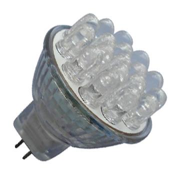
White LED usually has four different driver circuit: (a) the voltage source and ballast resistors, (b) current source and ballast resistors, (c) multiple current sources, (d) a current source driver series led lights.

Each white LED forward voltage (Vf) the impact of the current regulation accuracy, depending on the structure of regulation circuit: (a) voltage source and ballast resistors, (b) current source and ballast resistors, (c) multiple current source or a current source connected in series LED. 6 LED Vf curve (three from vendor A and B) are shown in the figure, the regulator output load curve and the LED’s Vf curve of intersection is the regulation of the operating point.
Circuits use a voltage regulator ballast resistors to control the LED current, the advantage of this structure there is considerable room to select the voltage source between the regulator and LED only need one connection endpoint; drawback is low efficiency, which is the main town resistor loss caused, in addition, its control of the LED forward current is not very accurate. Figure 5a test curve can be seen six different LED current range: 14.2mA to 18.4mA average luminance than the manufacturers provided by vendor A LED B is higher, the work of currents higher than 2mA.
The MAX1910 is this structure, this circuit can drive the same vendor products in the same batch to obtain good results. In the above circuit to provide the same current conditions, you can reduce the ballast resistors to reduce power consumption by half.Figure 5b shows the range of six different LED drive current: 15.4mA to 19.6mA, the LED current changes provided by the manufacturer A smaller average from vendor A and vendor B LED control current is the same: 17.5mA. The defects of this structure is the ballast resistor power consumption is still large, and the LED current matching is not very good. However, this circuit a good compromise between performance and ease of circuit.
The current regulation accuracy and matching of the individual current regulator. The MAX1570 uses a current source structure, the current accuracy of 2%, matching up to 0.3%. Low dropout current regulator, you can get higher efficiency. Figure 5c shows that all tested six white LED flood lights current is maintained at a stable 17.5mA, eliminating the need for ballast resistors, which can effectively save board space, but four terminals are required between the regulator and LED. This circuit can provide a high level of performance is based on the competition program of the inductor structure.
Lower feedback threshold to further reduce the sense resistor’s power consumption, because the LEDs are arranged in series connection, and under any working conditions are able to make the LED brightness is consistent. The current accuracy depends on the accuracy of the regulator’s feedback threshold from the LED’s forward voltage variations.The MAX1848 and MAX1561 are two typical examples of this current regulator circuit, conversion efficiency (PLED / PIN) can reach 87% (3 series LED) or 84% (6 LEDs in series). Another advantage of this circuit is between the regulator and LED only requires two connection endpoints, provide some flexibility for the user’s design. However, because the circuit uses inductance, a larger size, higher cost compared with the above-mentioned program, EMI radiation is also larger.
