rgb led mood light and top design

This paper mainly discusses the microcontroller-based LED driver. It looks at the microcontroller as the core of the system can be used in a variety of different topology. It also discussed in detail the tradeoffs of various topologies, and focus on their main features and limitations: communication, voltage and current capacity, dimming technology, as well as switching speed, etc..

What is the high brightness LED lights, and what it needs to drive?

rgb led mood light and top design

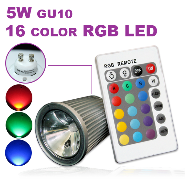
High-brightness light-emitting diodes (HI-LEDs) is a semiconductor device that only allows current to flow in one direction. It is into the PN structure formed by the combination of the two semiconductor materials. The high-brightness LED and standard LED difference is that their output power. Traditional LED output power is generally limited to less than 50 mW, and high-brightness LEDs up to 1-5 watts.

Exceeds the internal threshold voltage in the forward voltage (VF), HI-LEDs, almost no forward current (IF) to flow through. If VF is further increased, the curve will be linear slope of a sudden rapid increase in the formation of a shape of the knee of the curve.

The output brightness of the LED forward current is proportional to, therefore, if the IF is not properly controlled, the output brightness may not accept the changes. In addition, if more than the maximum specified by the manufacturer IF restrictions could severely shorten the life of the LED.

The high brightness LED flood lights electronic drive control, the main function of these electronic drive to form a constant current source. Using the techniques described later in this article, these circuits can provide a luminous intensity control can also compensate for temperature changes in certain circumstances.

To ensure that systems provide color consistency, HI-LED manufacturers recommend constant nominal current pulse output of the LED brightness adjustment.

Simple topology and its trade-offs

The challenges faced by the design of high-brightness LED driver is to construct a well-controlled, programmable, stable current source, but also high efficiency.

1, using a series resistor (linear method)

The easiest way to adjust the current is to add a series resistor. The advantage is low cost, simple to implement, and not due to switching noise. Unfortunately, this topology has two main shortcomings: First, the substantial loss on the resistor lead to lower efficiency of the system; Second, it can not change the luminosity. Moreover, such programs need to use a voltage regulator to constant current. For example, if we assume that VDD is 5 volts, the VF of the LED is 3.0 volts, so if you need to generate 350 mA constant current, you will need: R = V / I, at this time R = (5V-3.0V ) / 350mA = 5.7Ω.

Can see that these values, R will consume 0.7 watts (almost equivalent to the power of the LED) R × I2, so the overall efficiency is inevitably less than 50%.

This method assumes a constant VDD and constant VF. In fact, VF will change as the temperature changes, making the current changes. Changes to minimize the overall current to a higher VDD can be caused by VF, but a huge loss in the resistor, thus further reducing efficiency.

When we construct a flow through the LED constant current, you need to find a way to set a different light. We know that these LED tube always requires its nominal current to drive, so we can use the programmable duty cycle on-off current, in order to achieve control of the luminosity.

2, using a linear current source

A transistor and / or an op amp can be very precise current is set to 350 mA. Unfortunately, the problem is still the overall efficiency and R power loss.

3, the use of low-end switches (switch-mode method)

Allows the inductor L current when the switch is turned on, rise, drop when the switch is disconnected, we can adjust the current flowing through the LED. With any inductive load when the switch is open, we need to provide a path for current.

When the current is reduced to the low current threshold (300mA), the switch turns on, and when the current threshold rose to a high current (400mA), the switch will disconnect.

This case, switch to low-end (hence the name), the method is very simple. Pass FET is simply its doors to the ends of plus 5V supply, which can be provided directly by an output port of the microcontroller. Moreover, this topology is no longer needed constant VDD voltage, even if the input voltage fluctuations, but also to maintain regulated current.


Current sensing resistor R must be located in the “high end” section of the circuit. If it is connected to the MOSFET source can only be measured on the switch turns on the LED current can not be used to adjust another threshold.


This topology looks like a front-end boost converter, which use N-channel low-cost FET’s advantage, but in R both ends of the voltage differential measurements to obtain the current flowing through the LED.


Please note that the switch actually provides two functions: First, it makes the inductor current can be adjusted; Second, it allows the adjustment of the luminosity.

rgb led mood lighting and current control

Small size, high light output and flash or continuous video recording lighting output power LED lights have been developed specifically for mobile phone camera, light source, but have been overwhelmed by make battery a heavier burden. This paper discusses the current mobile phone camera light applications to optimize the efficiency, accuracy and control LED current power IC products and application technology.

rgb led mood lighting and current control

A function of more and more popular in the phone built-in digital camera that can shoot high-resolution still and video images. With the wide bandwidth of 3G networks roll out, the demand for higher resolution photos as well as new applications (such as video conferencing) to enhance the performance of the integrated camera. High-power white light source in the camera when used indoors or in dim light, the camera performance enhancements also put forward higher requirements. The white LED lamps are already widely used in the color display backlight, but also become the main light source for camera phones. The white LED has a combination of stylish mobile handset designers the required performance: small size, high light output and flash or continuous video capture lighting. The output power LEDs have been developed specifically for the integrated camera light source. Although these dedicated camera LED is ideal for landscape lighting, but they are also the consumption of the battery is another important factor.


From the system designer’s point of view, there are three main problems with driving high current white LED: 1. To provide efficient power; 2 to adjust the LED current; camera light source is turned off to ensure that the LED power supply is completely cut off. Like an ordinary diode, the electrical characteristics of high current white LED forward voltage is 3.4V or a typical 350mA forward current (see Table 1).
Increase the LED current (“flash” mode, 500mA-700mA or more) will cause a higher forward voltage. The low current (“torch” or “video capture” mode, 100mA-350mA) to produce a low forward voltage. The forward voltage will decrease as the temperature increases, will have hundreds of millivolts of drift in the temperature range of the phone work as a diode forward voltage. Therefore, effective to provide LED power supply is very challenging, LED forward voltage due to different working conditions may be higher or lower than the voltage of the lithium.

LED driver should be applied to the buck and boost DC / DC conversion, with minimal pressure drop in the current control circuit to adjust the LED current.


If two or more parallel LEDs use a camera light, due to the great changes between any two LED’s forward voltage drop, therefore need some additional devices to ensure current matching. The most obvious way is the LED in series, the boost converter works well. If, however, need to be connected in parallel, the solution must be able to provide independent current control of each LED. In any way, the current control circuit in the current-sensing resistor should be at the lowest possible pressure drop. Another complex points in the camera light applications from as low as a microamp forward current-current LED visible light. No inherent LED disconnect, needs to be a separate switch in series on the LED to ensure the shutdown, the LED will not have a current flows through.

High power LEDs produce visible light is very simple, but in the existing design to produce high-performance power supply and current control solution is very difficult. In these applications, there is no dedicated power supply IC to solve the above problem, the battery life will still suffer. Linear Technology’s LTC3453 is specifically designed to optimize the efficiency, accuracy and control LED current  in the current camera light applications.
LTC3453 use of a synchronous buck – boost power supply and programmable low-dropout current source to adjust the LED bulbs current. Devices based on VIN and LED forward voltage synchronous buck, synchronous boost, as well as four switch buck – boost mode automatically converted. Each current source has its own independent control loop can be adjusted in a very low LED pin voltage currents to reduce power consumption. Truly cut off the LED current source can be turned off. 4 LED current source (LED1 to LED4) LEDs can be connected in parallel or together to jointly drive a single high output LED. By regulating VOUT to ensure that all current source is the minimum voltage of the regulator state, the overall efficiency can be optimized. Within the scope of the entire lithium batteries and LED forward voltage synchronous buck – boost topology, the efficiency of the “flashlight” mode is greater than 90%, increased by 20% to 30% than ordinary step-up solution.

rgb led rope lights and Luxeon led

The high output from the Luxeon and Nichia 1W white LED 12W incandescent lamps of similar brightness level, while the power consumption of only 1W, and the service life of up to 50,000 hours or more. For many light bulb applications, these devices is expected to achieve significant energy saving effect, and reduce maintenance costs. However, in order to maintain the correct brightness, must be a constant current to drive these LED lights. The range of process and temperature within the limits of the forward voltage drop of 2.8V to 4.0V. Circuit for driving the LED at the same time maintain a constant current drive to compensate for the forward voltage changes. The boost circuit is usually voltage feedback switching converter with additional circuitry to detect the output current (not voltage). This leads to the circuit structure is complicated and inefficient.
The LTC3490 provides a way for single or dual battery voltage is raised to the desired LED forward voltage and to adjust the current through the LED load a simple solution. The high frequency (1.3MHz) operation allows the use of small value inductors and capacitors. The current sense resistor and loop compensation components are built, thus reducing the number of components. The LTC3490 is a synchronous converter, eliminating the rectifier diode and the associated efficiency loss. Components needed for just the boost inductor and an output filter capacitor. Shutdown and dimming feature adds a small amount of resistance, and, in some cases also propose to introduce an input capacitor.

Circuit Description

The LTC3490 is a synchronous boost converter. Its box is shown in Figure 1. The use of a low-voltage startup circuit, it can start under normal conditions of input voltage down to 0.9V. When the output voltage exceeds 2.3V, the boost circuit will be connected to the start-up circuit is turned off. The boost converter is a fixed frequency current mode architecture.
the LTC3490 block diagram

LED current in the high pressure side of the internal 0.1Ω resistor to detect, which allows the LED tubes to negative ground. A sense amplifier is responsible for the voltage to be compared with the reference current flow through a ratiometric match 19.2Ω resistor. Detection voltage differential calculus, and for the setting of the PWM controller. Therefore, LED current is constant, this has nothing to do with the LED forward voltage.

Two battery applications, the LTC3490 efficiency up to 90%; in single cell applications, the LTC3490 efficiency higher than 70%.
the LTC3490’s efficiency

Overvoltage protection

Current sensing controller may drive the output voltage to the devastating levels (if there is no load), so, you need to output overvoltage protection. If the LED panel from the circuit is removed or fails, it will happen. As long as the output current is below 350mA, the output voltage will continue to climb and there may be damage to the LTC3490 in the case of the overvoltage protection circuit. When the output voltage higher than 4.5V, an overvoltage detector forces the LTC3490 into shutdown mode. Overvoltage detector to keep connected to the state, will resume normal operation when the output voltage drops below 4.5V.

Dimming function

The LTC3490 can use the CTRL / SHDN pin to gradually reduce the LED current. CTRL / SHDN input has three functions: stop, dimming control and constant current output. The pin with a proportional relationship exists between the VIN pin voltage, which makes using a simple resistor divider to set the current value. When the CTRL / SHDN pin voltage is below 0.2? The VIN, the device is in shutdown mode, while the absorption current is very small. When the CTRL / SHDN pin voltage is higher than 0.9? The VIN, the device is 350mA constant current mode. When the VIN between the CTRL / SHDN pin voltage is 0.2? The VIN and 0.9?, LED current from 0mA to 350mA linear change.

Low-battery detection

rgb led rope lights and Luxeon led

The LTC3490 provides two low-battery detection level. These level set by CELLS pin, for the number of the section indicates that the battery. CELLS pin is low, low battery detection level is set to 1.0V, and when connected to VIN CELLS, low battery detection level was set to 2.0V. Which correspond to single and double battery operation. When the battery voltage falls below the detection level / LOBAT pin on an open-drain output is pulled low. The output can be used to drive an indicator, or feedback to the CTRL / SHDN pin to reduce the LED current, thus extending the remaining running time of the battery.

Shutdown the LTC3490 when there is an undervoltage lockout circuit, the circuit in the battery voltage drops below 0.8V per section. This can prevent the battery current is too large (single cell), and uneven-discharge Ni-MH battery, reverse battery (two batteries).

Battery reality check

The battery there is a so-called “discharge recovery” phenomenon. When to move away load from a battery is almost exhausted battery, the battery terminal voltage will be restored to a surprisingly high voltage. LTC3490 when a nearly depleted battery dead battery shutdown transition occurs, the decrease of the absorption current makes the battery voltage can be restored. This will be re-connected to the LTC3490, and load again added to the battery. At this point, the battery voltage will drop to once again trigger the shutdown operation. This phenomenon has led to the LTC3490 quickly switched on and off the LED current. Observations: When the battery charge is close to exhausted, the average LED current decreases slowly. The LTC3490 provides a simple solution using alkaline batteries or Ni-MH battery to drive the high-output white LED’s. It has the characteristics of high efficiency and less number of components.

Light distribution design for high-power LED tunnel lights

1)       Select suitable lighting sources. Lumen output per Watt (also named power efficiency) is always a notion that determines the performance of LED lights, including LED tunnel lights. Theoretically, competent LED tunnel lights should have power efficiencies larger than 80lm/W. After a three-year rapid development, the majority of LED tunnel lamps that sold in the market has reached power consumption as much as 90lm/W, following by the increase of brightness. OSRAM provided more sophisticated LED lighting sources for high-power LED tunnel lights. Natural White/Cool White (4000-6000K) is more common among LED tunnel lamps, which can provide a higher CRI and less “Bright/Black Hole Effect”.


1) Select suitable lighting sources. Lumen output per Watt (also named power efficiency) is always a notion that determines the performance of LED lighting products, including LED tunnel lights.


2)       Light distribution design. According to the specific requirements of tunnel lighting, optical principles and the one-direction property of LEDs, different tunnel segments should apply different light fixtures (different light distributions). Once brightness and illuminance are satisfied, the reasonable consideration of light distribution can save even more energy. In the entrance section, accommodative section, transition section and exit section asymmetric illumination (backlighting mode) should be used. Under the same lighting circumstances, in comparison with traditional high pressure sodium lamps, LED tunnel lamps can increase the light intensity near the ground by 21%. Meanwhile, the high directivity can eliminate most of glare. In the middle section (basic section) of tunnels, there are several commonly used light distribution applications: light-concentrated distribution, side-emitting distribution, Lambert distribution, etc.. Light distribution varies depending on different situations. For example, road lighting should use batwing distribution, and spot light should use light-concentrated distribution. Due to the particularity of tunnel lighting, LED tunnel lights have a relatively compact arrangement. Besides, the light distribution will differ from road lighting. Generally, batwing and Lambert are commonly used, since both of them can meet the requirements of even illumination within a large area. In the same luminous flux conditions, high-power LED tunnel lights used these two light distribution can increase the light intensity near the ground about 64%.


The development and producing of high-power LED tunnel lights provide more opportunities for national railway lighting, highway lighting and tunnel lighting, having them expand the market furthermore. It not only filled the gaps of new tunnel lighting source technology, but also promoted the development of low-carbon environmental protection process.

rgb led sign and solution

White LED has been widely used in handheld devices such as mobile phones as a color LCD screen backlight and keypad light. Color LED is a good indicator of the situation reported to the user calls and battery charging. The brightness of the LED lights current is proportional to the voltage must be high enough so that they conduction. Now the most popular battery is a lithium battery, the voltage is usually 3.6V or so, but as the battery discharges, the voltage will drop. For these reasons, the LED can not directly use this battery-powered, you also need an adjustable boost converter. Adjustable charge pump solution is very popular, especially in the total output current less than 100mA of simple and low-cost applications.

rgb led sign and solution

Different current drive LED

Adjustable output charge pump, such as Catalyst’s CAT3200-5 is one of the ideal LED driver can provide up to 100mA 5V regulator output load current. For LCD backlight white LED current is 20mA, the forward voltage VF of approximately 3.4V. The current through each LED tubes series resistor to set the resistance is also known as ballast resistors (see Figure 1). This structure allows parallel through different current in the LED. Larger resistance value smaller means that the LED current. In Equation 1, the approximate draw of the LED current (ignoring interconnect losses).

adjustable output charge pump applications

Formula 1: VOUT = the VF + (LED current × RS).

, VF is the LED forward voltage, RS is the series resistance.

The stability of the output voltage VOUT 5V, take into account when the forward voltage VF of 3.4V when the LED current is 20mA, RS = (5V-3.4V) / 20mA, or 80 ohms. In this example, three white LED display backlight, two color LED (red and blue) as the indicator. Each color LEDs have different forward voltage characteristics. The red LED forward voltage is very low, 20mA of current when voltage is typically 2.8V. Indicator LED is not used for lighting, so its current is smaller than the backlight LED tube.


the application of the adjustable current charge pump

The CAT3200-5 of the charge pump is one kind of voltage doubler, and only needs a large capacitor as the accumulation of container, the charge transfer from input to output. It is recommended to use a 1μF ceramic capacitor. All external components of the other two 1μF capacitors, were placed in the input and output pins.

Market there are still other LED driver implementations, such as inductor boost or charge pump current control. Inductor boost drive with an inductance to the input voltage is increased to drive several LEDs in series, The advantage is that these LED provide the same current, but this structure is not suitable for the above application examples. Another LED drive current control of the charge pump, by using the on-chip current regulation, a separate LED channels can drive an LED. In this case, the size of the LED current set by external resistors. In a more complex drives, via a digital interface can be programmed into the chip inside to go. The advantage of this structure is no longer needed for ballast resistors. Since all the LED current is the same, so this solution is not suitable for the applications we discuss.

The power supply with a series resistance of the electrical schematic Figure

The most critical issues often appear when the system is powered on. When the enable input pin of the signal from a logic low to logic high conversion, the device turns on and charge a large capacitor. Results in a very short period of time input current increases rapidly, resulting in the so-called “surge” current. Used to describe the advantages of an indicator of the power management chip is how did it perform in the monitoring of the input current. High surge current risks associated with internal rail voltage (VRAIL) instantly drop and affect the system operation. The decline in rail voltage power supply output impedance RS and interconnect impedance RINTER function (see Figure 3).

System rail voltage is calculated as follows: VRAIL = VBAT-IIN × (RSINTER,

Which, VBAT is the battery voltage, IIN is the input current. For example, if the series resistance of the sum of 1.5 (inrush current is 0.5A, then the rail voltage: VRAIL = 3.6V (0.5A × 1.5 ohm) = 2.85V.


VIN 3.3V and the load current of 100mA power on
Such a low voltage can cause a system crash. A way to reduce the inrush current of the battery output is to increase the input capacitance of CIN. As a result, most of the large capacitor charging current provided by the capacitor, CIN can reduce the inrush current. Figure 4 depicts the input capacitance of 1μF and 4.75μF input current and output voltage waveform.

The input current waveform when the linear growth in the output voltage to the rated 5V input current is gradually increased. The initial current spikes because only a very short period of 2μs duration, so no harm, it has little effect on the input voltage.

rgb led tape light and timer

For the first time the input voltage VS D1 will enable the storage capacitor C1 is charged until its voltage slightly lower than the VS. Initially, the transistor Q2 in a closed state, IC1’s reset input is high, the output (OUTPUT) is high, so the current through R1 to C2 charging.

During this time, R4 pull the discharge side (DISCHARGE) turns on transistor Q1, the current in the inductor L1 IL began to slash increases. Q1 is saturated, so the D3 and the LED lights in reverse bias state.

When the C2 voltage more than IC1 pin 6 threshold voltage (THRESHOLD), output (OUTPUT) and the discharge side (DISCHARGE) goes low, Q1 is cutoff. Back electromotive force generated across the L1, instantly elevated to the VA of the LED anode voltage, VA, is greater than the VS, the LED is lit. At this time, the diode D3 is forward biased state, and pull IC1’s input voltage V + until more than VS ~~ 4V.

Then, C2, once the rapid discharge through the transistor D2 and resistor R2, ready for the next cycle. If the proper choice of the resistance of R5 and R6, Q2 turns on the LED reset input at the same time. L1 stored energy is depleted, the LED and transistor D3 re-enter the reverse bias state, the VA is reduced to a lower level. Q2 is turned off immediately, and allow the the IC1 start another cycle, C2 begins again charging through R1. The process is repeated thousands of times per second, so the LED can be lit continuously.

This circuit uses three “tricks” to optimize performance. Transistor D3, since the gain can increase the input voltage of the timer, and even in VS drops below 1V, the circuit can also continue to work properly. In addition, through R4 Q1 enhance the base gate drive.

rgb led tape light and timer

Second, through Q2 feedback to ensure that the L1 energy is exhausted, new cycle can begin, so to maximize the average LED current.

Q1 is not the timer output side, but driven by a timer drain discharge terminal, the base drive does not depend on the performance of the 555 timer output terminal current source.

Transistor Q1 must be low in saturated type, the driving time for tON: tON = K × R1 × C2,

Where K is a constant determined by the actual use of the 555 timer type.

LED grow lights peak current is approximately equal to the maximum induced current IL (MAX): IL (MAX) = [(VS-VCE (SAT)) / L1] × tON Q1’s saturation voltage is low, for example, is lower than 50mV, then the VCE (SAT) can be neglected, the above equation simplified to: IL (MAX) = (VS/L1) × tON

Therefore, for a specific VS values, select R1, C2 and L1 values ​​can be IL (MAX), the maximum, which does not exceed the peak current rating of the LED to achieve maximum brightness.

Must be the appropriate choice of resistor R5 and R6, to ensure that VA = Q2 is turned off (in the case of incentives for the first time), the LED forward bias (VA> VS) conduction. Q2 itself must be a high current gain of small signal devices.

In order to achieve high efficiency, low voltage operation mode, you must use the CMOS timer, such as Intersil’s ICM7555 or TI’s TLC555. These types of timers are running under a 2.0V low voltage special features. In addition, their internal discharge transistor to pin 7 of voltage down to 100mV or even lower, to ensure that Q1 is completely turned off.
In a test circuit, IC1 TLC555, Q1 = ZTX649, Q2 = BC546, L1 = 100 μH, R5 = 56 kΩ, R6 = 10kΩ, that the circuit in the VS is equal to the low voltage of 1.0V to start. This circuit can Lumileds (www.lumileds.com) white LED to the best brightness.

The rise time of the transistor Q1 (tON) about 20 μs, making about 300 mA VS = 1.5 V when the peak inductor current. But to change the value of C2, R1, C2 of R1, L1 can change the peak inductor current, the ICM7555 also achieve the same performance, the minimum turn-on voltage will be slightly higher than 1.2V.

This circuit is ideal for a single LED application, because even if the input voltage drops below 1.0 V, it can make the LED flood lights to maintain sufficient brightness. Of course, two or more LEDs in series with its brightness will be reduced accordingly.

round led panel light and convertor design

Many of today’s portable consumer electronic products has a display screen, such as mobile phones, PDAs, and MP3 player, the type and size of the screen is usually determined according to the application, but the design engineer must be responsible for its design of power supply and backlight circuit. The white LED backlight program to select the most commonly used by the portable consumer electronics products.

round led panel light and convertor design

The main objective is to drive white LED lights to produce the forward current through the device, which can be a constant voltage source or constant current source to achieve.  However, this method has its shortcomings, the ballast resistor will limit the current through the nonlinear VI curve of the white LED steady flow capacity of this method is very poor; In addition, as long as the applied voltage or white LED forward voltage ( VF) any changes in the white LED current will change. Rated forward voltage of 3.6 V, a 20mA current through the white LED in Figure 1, if the temperature or process changes this voltage into 4.0V (still in the normal 3V to 4V tolerance range), the forward current will drop to 14mA; In other words, the forward voltage change of 11%, the forward current is 30% of the significant changes. Extreme changes of this white LED current will affect the display brightness, which is unacceptable in many applications.


Ideal for white LED down lights drive mode using a constant current source, it can avoid the white LED forward voltage change caused by the current change constant forward current can be controlled, can provide a constant display brightness can be controlled. Constant current source is very simple controller without the power output regulator, but as shown in Figure 2, the direct voltage across the resistor for current sensing regulator, the white LED current from the power to determine the value of the reference voltage supply and current sensing resistor value. Most monitors require more than one white LED designers the flexibility to drive multiple white LEDs, they should be all white LED in series, to ensure that each white LED current is the same. To promote white LEDs in parallel, each white LED must be a ballast resistor in series to avoid differences between the current through them, but these resistors will waste power and reduce the circuit efficiency.


Inductive drive and charge pump drive


IC designed to drive white LED provides a constant current, most of which is inductive or charge pump-based solutions, both solutions have their own advantages and disadvantages. The switched capacitor charge pump solutions, or solution, the use of discrete capacitors to the power from the input sent to the output side, the whole process without using any inductors, it is a popular solution. The small size of the charge pump power supply, the design is also very simple, select the components usually just pick and choose the appropriate capacitors according to component specifications. The charge pump solutions, the main drawback is that it can only provide limited output voltage range, the vast majority of the conversion ratio of the charge pump IC can only reach up to twice the input voltage, which means that the output voltage can not be higher than twice the input voltage If you want to use a charge pump to drive more than one white LED, you must use the parallel drive way. When only the output voltage regulated charge pump to drive multiple white LED ballast resistor must be used to prevent the current uneven distribution of these resistors will reduce battery life.


Inductive solutions for small size, high efficiency, providing longer battery life for the vast majority of consumer products. This article will prove that the designer can adjust the inductance converter efficiency in order to achieve an optimal balance between size and efficiency. As most of the inductive solutions are based on the boost converte, up to drive six or seven white LEDs in series, this practice has its merits, because many of the display’s built-in white LED are used series model; even if no built-in white LED grow lights display screen, most engineers will be connected in series. The backlight driver and the white LED is usually in a different circuit board must be power from a circuit board connected to a circuit board. Drive five parallel white LED totaling six pin connector, the drive to five white LEDs connected in series requires only two pins.

s11 led bulb and power switch

Automotive lighting assembly suppliers are considering the use of LED lights devices with high-intensity discharge (HID) lighting competition. First, the LED device driver circuit complexity of the HID lamp. HID lamps require high voltage ballast circuit starts an arc in the HID lamp, and in the Kai-arc needs to adjust its voltage output to maintain constant power supply HID lamps. From the electromagnetic compatibility (EMC) point of view, these high-voltage circuits are prone to noise, further hampered the technology for use in the automotive sector. Finally, the cost of the LED devices continued to decline, to make this technology more and more attractive for cost-sensitive automotive market.

s11 led bulb and power switch

A typical LED headlamp application requirements to provide more than about 25 watts of power to the LED array. One of the advantages of the LED components is high efficiency, drive electronic components should also improve efficiency, to give full play to the advantages of LED street lights technology. Consider some kind of switching power supply (SMPS) to achieve this goal (see Figure 1). But most of the SMPS design goal is to adjust the voltage rather than current.
For this application, select the buck topology. Limit of the input voltage (VBATT = 9 V min.) And the array of forward voltage drop (2xVF = 8.0 V, VFMAX = 4 V IF = 350 mA) to determine the expectations of a buck topology to meet these requirements, it is reasonable to . The method of driving the LED is switch / voltage stability, and then flows through the LED current adjusted by pulse width modulation. In the path of the LED and switch, you need a current limiting resistor in series in order to avoid too much current flows through the potential damage. This series resistance power consumption can lead to reduced efficiency.

However, SMPS with conducive to the steady flow component. Simplified buck regulator circuit shown in Figure 2.
Simplified schematic of the buck regulator
More careful observation of the energy storage elements in this design can be found some interesting points. Current through the inductor can be seen as both exchanges is also a DC component. Consider the work of SMPS inductor in discontinuous mode (inductor current waveform, see Figure 3). In this application, the DC component is of particular concern. Because the current is the key parameter, and adjust the current to the load is the main objective of this circuit. Should also remember that the exchange of components to minimize the target.
continuous mode flow through the inductor current waveform
In addition, because they do not consider the output voltage, and it changes with the LED devices, and thus does not require the same like a conventional voltage regulator circuit to consider this node regulator task. When the inductor charging and to help provide energy to the LED down lights array, the output capacitor current during this period Traditional regulator, this component will be retained.


samsung led lighting products and design method

With the development of white LED lights, it’s more widely applied. In the past, the white LED is the most common application is as a small-size color LCD backlight. White LED brightness increase, its application has spread to other areas, such as a flashlight or cell phone camera auxiliary lighting. This paper describes a general boost chip to drive the efficient high-current LED circuit.
Circuit design

samsung led lighting products and design method

General white LED current is about 20mA, but the high brightness LED 200 to 300mA current. If the product needs to use three to four high-brightness white LED, the brightness average general practice is to string them connected together. On the market, most of the white LED driver chip can only drive 20mA. Hit a series high current LED applications will have to think of other ways. Intersil’s EL7516 is a typical step-up chip, this chip operates at 1.2MHz fixed-frequency PWM mode, built-in 1.5A, 200mΩ MOSFETs. Figure 1 shows the the EL7516 typical application circuit. DC-DC boost the role of EL7516 will be 2.7 ~ 5.5V input into a constant voltage of 12V. General PWM control chip, the FB pin is connected to the error amplifier is compared with 1.3V. R1, R2 resistor value is selected to set the output voltage.


The EL7516 Boost Application Circuit

EL7516 voltage circuit into a constant-current LED drive circuit is very simple. Shown in Figure 2, the FB pin of R1 replaced by LED, change R2 can adjust the current through the LED. The value of R2 can be selected from the following formula: R2 = VFB / Iled where VFB is the FB pin voltage, that is, 1.3V; Iled current through the LED.

Standard LED driver circuit

EL7516 used to drive four high-brightness white LED tube

R2 by 300mA, the resistance of the power consumption is close to 0.39W. Such a great power not only affect the efficiency, but also need to use the relatively large size of the resistance in order to accept the 0.39W of heat. In general, these applications are battery-powered, efficiency and line PCB space requirements are more stringent now let us look at how to improve the efficiency of this line.

Regardless of the circuit changes how EL7516 will adjust the duty cycle so that the FB voltage to maintain 1.3V. The assumption D1 positive voltage drop is 0.6V, the voltage drop across R2 is about 0.7V. To maintain a 300mA LED current, R2 can be used to 2.3Ω. R2 power consumption also dropped from the original 0.39W 0.21W. Although the power consumption has been reduced, but R2 have to use a half-watt resistor to this circuit.

A cheap TL431 added to the circuit as a 2.5V reference. As mentioned earlier, the EL7516 will keep the FB in 1.3V; so the current through R4 is: (2.5-1.3) / 20k = 60mA. FB is a high-impedance pins, we assume that this 60mA full inflow of R5, made the same 1.2V voltage drop. 0.1V, the rest of the R2 to complete. In order to facilitate the purchase, R2 is selected as 0.39Ω. So the current through the LED is about: 0.1/0.39 = 255mA. R2, the power consumption is significantly reduced to: 0.1 × 0.255 = 26mW.

Conclusion

Can be seen from the above experiments, minor changes can greatly improve the efficiency of high-current LED panel in the circuit. Experiments, we use a 5V input. The practical application is likely to be a single lithium battery power supply. The EL7516 minimum operating voltage of 2.3V, so apply to a single lithium battery power supply. EL7516 built-in MOSFET peak current (1.3A min) protection, such as the lithium battery voltage dropped below 3V, drive four LEDs may trigger the current protection. Such as the need to 3V below work best to reduce the output for the three LEDs.

sbc led bulb and led design

When the output voltage may be higher than the input voltage may be lower than the discontinuous buck-boost converter peak current mode control LED driver is a good choice. However, this buck-boost converter used to drive design, the LED voltage change will change the LED current to LED open circuit will produce high output voltage, thereby damaging the converter. This article will discuss in detail this applied to the LED lights converter design, and describe a variety of overcoming the inherent shortcomings of the method.

sbc led bulb and led design

The light-emitting diode (LED street lights) applications have been for many years, with the latest technological advances, is becoming a strong competitor in the lighting market. The new high-brightness LED has a long life (100,000 hours) and high efficiency (about 30 lumens / watt). The past three decades, the LED light output brightness every 18 ~ 24 will double, and this growth momentum will continue, this trend is called Haitz law, which is equivalent LED Moore’s Law.


Figure 1a: LED connected in parallel. Figure 1b: LED series connection.
Electrically similar to the LED and diode is a one-way conductive (although the reverse blocking capability is not very good, high reverse voltage is very easy to damage the LED), similar to the conventional diode low dynamic impedance VI characteristics. In addition, LEDs are generally safe conduction of the rated current (rated current of the high brightness LED typically is 350mA or 700mA). Rated current, LED forward voltage drop of the difference may be relatively large, typically 350mA white LED voltage drop between 3 to 4V.

The drive LED controlled DC current. In order to make the long life of the LED, the LED current ripple must be very low, and high ripple current causes the LED to produce large resistive power consumption, reduces the LED life. LED driver circuit is the need for higher efficiency, because the overall efficiency depends not only on the LED drive circuit. Work in the current control mode switching converter is ideal drive options to meet LED applications with high power and high efficiency requirements.

Drive multiple LEDs also need careful consideration. For the following two reasons, is not recommended as shown in Figure 1a as parallel LED strings: dynamic impedance and forward voltage drop of each LED is not the same, if there is no external current circuit (current mirror), impossible to guarantee that flow through the LED the same current; an LED failure will make the LED string is disconnected, resulting in LED current is distributed between the rest of the LED string, which will lead to increased current in the LED string, and may damage the LED.

Therefore, a better approach is the LED in series. The disadvantage is that if one LED fails, the entire LED string will stop working. An easy way to let the rest of the LED string to continue working is a Zener diode (rated voltage greater than the maximum LED voltage) shown in each (or group) LED in parallel, as shown in Figure 1b. In this way, any one LED fails, its current will flow to the rest of the Zener diode LED string can still work.

The basic single-stage switching converter can be divided into three categories: the buck converter, boost converter and buck-boost converter. When the LED string voltage is lower than the input voltage, the buck converter (Figure 2a) is the ideal choice; when the input voltage is always lower than the string output voltage, the boost converter is more appropriate (Figure 2b); when The output voltage may be higher than may be lower than the input voltage (caused by changes in output or input), the buck-boost converter (Figure 2c) is more appropriate. The disadvantage of the boost converter, input voltage transients (allows input voltage increases and exceeds the output voltage) will result in the LED upstream a large current (low dynamic impedance load), thereby damaging the LED. Buck-boost converter can replace the boost converter input voltage transient does not affect the LED current.

Buck-boost converter works

LED driver for low voltage applications, the buck-boost converter is a good choice. A variety of reasons, some of which are listed below: They can be used above and below the voltage of the input voltage to drive the LED grow lights strings (boost and buck); high efficiency (it is easy to reach more than 85%); discontinuous suppress the input voltage changes of work mode (to provide good line voltage regulation); peak current control mode allows the converter to regulate the LED current, without the need for complex compensation (simplified design); very easy to implement linear and PWM LED dimming; switch transistor failure will not damage the LED.
Figure 2a: buck converter. Figure 2b: boost converter. Figure 2c: buck-boost converter.

However, this approach there are still two shortcomings: the peak current controlled and discontinuous current mode buck-boost converter is a constant power converter, so any changes will cause the LED current in the LED string voltage corresponding change ; Another problem is that LED open circuit condition in the circuit to produce damage to the high voltage of the converter; In addition, additional circuitry is required to a constant power converter into a constant current converter, and protection in the case of no-load converter.

Figure 3 for the lifting pressure converter application circuit diagram, the controller has built-in used to set the switching frequency of the oscillator. The beginning of the switching cycle, Q1 turns on. Due to the input voltage VIN added to the inductor, the inductor current (iL (t)) from zero (initial steady state) began to rise.