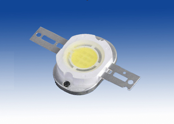
TSMC: the driving voltage of LED drivers can reach up to 60V

TSMC promoted new BCD (Bipolar, CMOS DMOS) module on 15th this month, which can be embedded into integrated LED drivers.


TSMC: the driving voltage of LED drivers can reach up to 60V


This new BCD technology used in LED drivers can provide a voltage range from 12V to 60V, supporting a variety of LED applications, including backlight of LCD display, LED screens, general lighting applications and vehicle lighting applications. There are several core digital module options, from 0.18 micrometer to 0.6 micrometer. Besides, CyberShuttle also provided TM carpool trial services, which support modules from 0.18 micrometer to 0.25 micrometer.


Draw support from multiple integrated features provided by the new technology, system BOM can be reduced. High voltage DMOS not only provides MOSFET switch integration to reduce the number of components, and integrates other electronic components, like high voltage bipolar transistors, high voltage / high precision capacitors, high resistance polysilicon Zener diode (Zenerdiode), etc., but also reduces the number of external component and significantly reduce the area of the circuit board.


DMOS supports the advanced drain-to-source-to-resistance (Rdson) effect in IC manufacturing. A specific 60V NLDMOS component, when VB>80V, the Rdson will be 72mohm-mm2, plus the extremely strong current driving capability, engineers can simply increase power efficiency via optimizing the component size. The reliable safe operation area (SOA) can also optimize power switches and driver circuits, making them better. Certainly, there are more detailed characteristics of analysis can also be used as result reference of IC design to achieve optimum chip size and reduce design budget of LED drivers.


In the aspect of COMS, 5V voltage is enough to support the Pulse Width Modulation Controller. 2.5V and 1.8V logic cores are common to higher levels of digital integration. In addition, compatible to logic circuits, memory options available for single writing and multiple writing, can also enhance the use of digital programming.


According to Mr. Xinsheng Liu, manager of electronic and industrial research and development department of TSMC, in terms of the integration of driver components, the new BCD manufacturing process of LED drivers is a highly sophisticated technology. Related process design kits (PDKs) emphasis on SPICE models with high accuracy, providing more convenient to single-chip design. In addition, MismatchingModEL can help improve the precision in multi-channel LED Tunnel Light driver designs.

residential led lighting systems and led drivers

Flyback LED drive GM, because the structure can be used for input voltage higher or lower than the required output voltage. In addition, when the flyback circuit operating in discontinuous inductor current mode, able to maintain a constant LED current, no additional control loop. The circuit described in this application note is based on highly integrated MAX16802 PWM LED driver IC.

Application

* LED track lighting

* Universal LED lighting

Feature

* 10.8V to 24V input voltage range

* Single 3.3V LED power supply, provide 350mA (typical) current (LED configuration structure, designed in accordance with the design steps)

* 29V (typical) anode to the maximum open circuit voltage

* 262kHz switching frequency

*-By-cycle current limit

* On / off control input

* Allows the use of low-frequency PWM signal to adjust the brightness

* You can adjust the circuit to adapt to the various forms of series, parallel LED configuration

Typical Application Circuit
Note: + VLED-VLED and LED lights connections, do not give circuitry.

Component list

Circuit topology

* Open-loop, non-isolated flyback LED drive is very general and easy to use. It has a number of advantages, and very popular. These benefits include:

* The need for an external control loop to adjust the LED current

* Non-continuous inductor current transfer reduces EMI emissions

* Lower switch conduction losses

* Simple circuit design process

LED voltage can be higher or lower than the input voltage

* A wide input voltage range

* Easy access to the PWM dimming signal

The biggest advantage is the cost of the following shortcomings:

* The LED current is limited by component tolerances, for example, the inductor and galvanometer comparator propagation delay

* Non-continuous inductor current mode, so that the topology is more suitable for low power applications

Design steps

The most important parameter is the LED current. The high-brightness LED current is generally a few hundred mA. In order to extend the working life of LED, the current must remain constant; power is essentially a current drive. There are several ways to achieve a simple and low-cost solution: using a dedicated current mode PWM controller IC, for example, while the MAX16802 is. The advantages of the device is:

* A high level of integration – required few external components

* Up to 262kHz switching frequency

* Tiny 8-pin μMAX

* Smaller galvanometer threshold, to reduce losses

* Accurate oscillation frequency, to help reduce the LED current changes

* On-chip voltage feedback amplifier can be used to limit the output open-circuit voltage

Given the LED parameters are:

Step 1: calculate the minimum input voltage, the best approximation of the duty cycle:

Where Rb is the ballast resistor R11 in the application circuit in this application is set to 1. VD is the forward voltage drop of the rectifier diode D1.

The known values ​​in the above equation:

Step 2: Calculate the peak inductor current approximation:

Kf is a critical error coefficient, set at 1.1.

The known values ​​into the above equation to get:

residential led lighting systems and led drivers

Step 3: Calculate the required inductance approximation, and select the less than and closest to the calculated value of the standard inductance:

Where L is the L1 in the application circuit; f is the switching frequency is equal to of 262kHz.

The known values ​​into the above equation to get:

Below this value, the closest standard value of 10μH.

Step 4: the process of passing through the flyback output power:

The output circuit power dissipation is equal to:

According to the principle of conservation of energy, the two formulas should be equal, you can get a more accurate peak inductor current:

Where L is the actual choice of standard inductance values.

Known values, we can get:

Step 5: Calculate the galvanometer resistance, derived by R9 and R10 in parallel; calculate the voltage detection voltage divider (if needed), consisting of R6 and R7.

The MAX16802 is the current limit threshold of 291mV. Therefore, R9, R10, R6 and R7 to meet the inductor peak current calculated in step 4.

Upon completion of this step, you can get the value of the various components of the application circuit, The circuit provides 12V, 350mA output. Because of the parasitics, the resistance value (R7) need to make proper adjustments to get the desired current.

Step 6: R1 and R2 are optional. They are used to adjust the + VLED to 29V. This is very useful output unexpected open. If the partial pressure of the above components, the output voltage is likely to rise, resulting in damage to the device.

Components C1 and R5 is optional, used to stabilize the voltage feedback loop. For the current application, you can not use these components.

shop led lights and led drivers

We developed an array of signal processing systems (led lights), due to the array antenna must be placed in the surrounding open area, and array signal processing unit is located in a circular array antenna central location, which requires a computer outside of the array signal processing unit in 1 ~ 2km between the duplex communication. Proportion in the time index in the entire system in order to reduce the data transmission time, the data transfer rate should be not less than the rate of E1 (2.048Mb / s), and ask the communications link is safe, reliable. Analysis of various data communication technologies, the final choice of a fiber-optic key road, and achieved satisfactory results.

A copper media data link

Also requires a higher data transmission rates and longer communication distance in the copper media link coding and modulation is difficult to meet the index requirements, but the high-speed modem is not only expensive, but the handshake process time-consuming random real-time requirements field of the transmission data will obviously not apply. The most important thing is that the traditional copper media link produces both electromagnetic interference signals, and also easily affected by electromagnetic interference, and difficult to meet the requirements of the EMC (electromagnetic compatibility) and EMI (electromagnetic interference) standards.

Analysis of two fiber-optic link

The traditional image of the people, the fiber used in short-distance communication is not economical, but it has a copper media key road incomparable advantages: ① fiber link is neither emit electromagnetic wave, is not affected, there is no interference between the fiber error rate is greatly reduced. The designers do not consider the incoming ambient noise may be coupled; ② fiber to provide a communication link between the two electrically isolated to eliminate the problems caused by ground potential between the long-distance equipment. Designers no longer have to impedance matching and a headache; ③ fiber-optic transmitter can be digital modulation driving circuit. Digital baseband signal through a simple line coding, you can directly drive the fiber optic transmitter.

Now, the price of fiber optic devices than ever before has been a sharp decline, With the cable price increases and the fiber-optic device prices to decline further in the future, when people choose fiber is no longer first consider the price factor. Therefore, considering the speed and distance indicators, select the appropriate type of fiber transceiver and its drive circuit, high performance and low cost fiber-optic communication key road, this is the focus of this paper to.

The choice of optical fiber communication devices

A basic fiber-optic communication system is very simple: an LED panel emitter electrical signals into optical signals, and the coupling into the transmission fiber, the optical signal through the fiber to reach the optical receiver, the received optical signal back into the original the electrical signal output.
· Cable options: general, quartz glass fiber due to its low loss, high bandwidth for long-distance communications links, such as Ethernet and FDDI standard specifies multimode 62.5/125μm quartz glass fiber. Thin core fiber requires high-precision connectors to reduce the coupling loss, low-cost cables and connectors for industrial applications. 1mm POF (Plymer Optical Fibers) and 200μm HCS (Hard Clad Silica) fiber is the best choice, they are the step-index multimode fiber.
1mm POF typical loss value at 650nm wavelength is 0.2dB / m, 200μm HCS fiber to only 8dB/km 650mm wavelength typical loss value, less in the 820nm wavelength. HCS fiber is the core of the quartz glass cladding is a patented high-strength polymers, not only increased the intensity of the optical fiber, and moisture, pollution prevention and the outer sheath of PVC 2.2mm. HCS fiber can work in a 40 ℃ ~ +85 ℃ temperature range, the erection of a temperature range of 20 ℃ to +85 ° C, in both performance and price to meet the system requirements.
· Operating wavelength choice: fiber optic communication system design must take into account the impact of fiber loss and dispersion of the system, due to loss and dispersion are related to the operating wavelength of the system, the operating wavelength choose to become a major problem in system design. Consider the system specifications and selected fiber, select the 820nm wavelength enables HCS fiber loss as low as 6dB/km dispersion has reached the minimum.
· Choice of light source: LED can be selected in the 820m wavelength light compared with the semiconductor laser, the LED drive circuit is simple and low cost.

shop led lights and led drivers
In summary, the cable selection 200μm HCS fiber optical transceiver device selection of the 820nm wavelength of the HP’s HFBR-0400 series. In the 1500m distance in the series HFBR-14X2/HFBR- 24X2 reach 5MBd rate of the operating temperature range from 40 ℃ to +85 ° C, ST, SMA, SC and FC, multiple port models to choose from. HFBR-14XZ type AlGaAs LED tubes with 820nm wavelength HFBR-24XZ internal integration of an IC chip including PIN photo detector, the DC amplifier, and the open collector output Schottky transistor, its output directly with popular TTL and CMOS IC connected.

4 A practical fiber optic LED driver circuit

The fiber optic duplex communication system in which the role of the driver circuit is to convert electrical power into optical power, and modulation of the transmission of electrical signals to the output of the light source, its light while providing the bias current and changes with the digital signal modulation current.

Design LED driver circuit must first consider the peak of the LED drive current, and if more than the peak drive current produced by the optical signal will overshoot phenomenon. Chong, resulting in the receiving device to cause the signal coupled from the amplifier noise, the results may be beyond the detection threshold of the comparator, causing the error. LED has extinguished than the features lit difficulties, it will produce a smearing, This phenomenon is particularly evident when using the serial driver circuit. The parallel drive mode can provide a low resistance channel for the carrier in the LED, thereby reducing the pulse width distortion and slow smearing.

Resistance RSI in the drive circuit is used to adjust the optical output power, be careful not to exceed the peak drive current of the LED, or optical signal will overshoot. Another circuit of the SN75451 with the characteristics of low impedance, high current rate, to avoid the long tail phenomenon.

Pulse width distortion (PWD) is a major factor to limit the rate of fiber-optic link, which is caused by transmission delay between the input and output are not equal. Noted that PWD is always positive, so we can take advantage of the RC circuit to delay the LED is lit.

The optical receiver circuit is an important part of the optical fiber communication system, its performance is good or bad is a comprehensive reflection of the optical fiber communication system performance. Its role is to optical fiber transmission over optical signals into electrical signals, then amplified and balanced, the decision circuit and restore the original signal of the transmitter.

The presence or absence of the commonly used optical signal in optical fiber transmission line, “1” and “0” code in order to avoid the long stream even “0” or long even “one”, conducive to the extraction of the clock, the need for coding circuit. Array signal processor is sent to the parallel data rate and conversion circuits.

How to select correct LED drivers IC

LED lighting will leap in the development in the near future. LED is widely recognized as a green clean light. The long life LED lights source, energy saving, easy application, the use of low-cost lighting in the home will be a flood of applications.

How to select correct LED drivers IC

In the field of LED lighting, the correct choice of the LED driver IC is essential. In order to reflect the characteristics of the LED lamp energy saving and long life. Good matching of the driver IC, the advantages of LED lighting can not be reflected. In the selection of LED drivers IC should be noted the performance indicators and how to use it?

The LED light source technology are getting mature. The per-watt light-emitting lumen rapid growth, and lead gradually decline to lower prices. 1W LED light source for example. The price in spring of 2008 is one-third of the price in spring of 2006, and it will dropped to fourth in year of 2009.

The high-energy, long life, and the environmental benefits of the superior performance of LED lamps are generally recognized.

1. High energy saving LED: DC drive, ultra-low power consumption(single tube 0.03-1W) electro-optical power conversion close to 100%, the same lighting effects than traditional energy sources more than 80%.

2. Long-life LED: LED light source is known as the longevity light. Solid cold light source, epoxy encapsulated, light body and no loose parts, it does not exist filament light easy to burn, heat deposition, the light fades and fast drawback life of up to  50000-100000 hours longer life than traditional light sources 10 times.

3. The LED environmental benefits: LED is a green light, the environmental benefits of better. No ultraviolet and infrared spectra, low in calories and no flicker, no radiation, and waste recycling, no pollution, and no mercury element, cold light source. It is safe to touch and belongs to a typical green lighting.

The working character of LED lighting source

The VF voltage of the LED lighting is very low, under normal circumstances is 2.75 to 3.8V, the IF is generally is 15 to 1400mA. LED driver IC output voltage is VFxN, VFx1 IF constant current at 15 ~~ 1,400 mA, LED lamps use LED light source has low power (IF 15 to 20mA) and high power (IF greater than 200mA) two kinds.

solar panel street lights and led drivers

LED power supply is also a supporting products currently on the market power quality is poor, the following businesses entering the bank to provide some knowledge of the LED drive power.

The characteristics of the LED drive power

(1) high reliability

Especially as the drive power of the LED lights installed in the high altitude, inconvenient repairs and maintenance spend.

(2) high efficiency

LED energy-saving products, the higher the efficiency of the drive power. Results cooling power installed in the fixture is very important. High efficiency power supply, the loss power, heat in the fixture, and reduces the temperature rise of the lamps. Beneficial to delay the LED light failure.

(3) high power factor

The power factor is the grid load requirements. Appliances generally less than 70 watts, there is no mandatory targets. Power is not a single electrical power factor on the grid has little effect, but the use of large amount of lighting at night, focus too much on similar load, the grid will produce a more serious pollution. 30 watts to 40 watts of LED drive power, said that in the near future, will power factors may have certain specifications.

solar panel street lights and led drivers

(4) drive way

Now common, there are two: one is a constant voltage source for the constant current source, each constant current source separately to each LED power supply. In this way, the combination of flexible, all the way to the LED fault, does not affect the other LED’s work, but the cost will be slightly higher. The other is a direct constant current power supply is in the Division Hui Bao “to drive the LED in series or parallel operation. Its advantage is low cost, but the flexibility is poor, but also to solve a LED fault, does not affect other LED running. These two forms co-exist within a certain period of time. Multi-channel constant-current output power supply, in terms of cost and performance. May be a future direction of the mainstream.

(5) Surge Protection

LED anti-surge capacity is relatively poor, especially the anti-reverse voltage capability. Is also important to strengthen this protection. Some LED lights installed in the outdoors, such as LED street lights. Kai rejection grid load and the induction of lightning from the grid system will invade a variety of surge, some surge can cause damage to the LED. Therefore, the analysis in Section Hui Bao “drive power in the surge protection should have a certain lack of frequent replacement as for power and lighting, LED drive power have to inhibit the intrusion of surge, the ability to protect the LED is not damaged.

(6) protection

Power in addition to conventional protection functions, the best increase in the constant current output LED temperature negative feedback to prevent the LED temperature is too high; to comply with the requirements of the safety and electromagnetic compatibility.

3, according to the drive mode.

(1) constant flow

Constant current drive circuit output current is constant, and the output DC voltage with the change of load resistance of different sizes within a certain range, load resistance is small, the output voltage, the greater the load resistance, the output voltage higher;

Not afraid of the constant current circuit load short circuit, but is prohibited to load completely open;

Constant current drive circuit driving the LED is an ideal, but the relatively higher prices;

Should be noted that the Maximum current and voltage values, which limits the number of the LED.

(2) The regulator type

When the parameters identified in the regulator circuit, the output voltage is fixed, the output current changes with changes in load;

The regulator circuit are not afraid of open-circuit load, but it is prohibited to load completely short-circuit;

Regulator drive circuit drives LED strings with a suitable resistor before each string of LED display brightness average;

The brightness will be affected by the rectifier from the voltage change.

4, the overall constant current and constant current work by road advantages and disadvantages

-By-channel constant current shortcomings more, the cost is relatively high compared with the overall constant current. But it can truly protect LED and extend the life of the LED-by-channel constant current is the future trend.

5, LED power less than

LED driver power supply shortage of reasons:

Production of LED lighting and related products, the company’s technical staff is not enough understanding of the switching power supply to make the power supply is working properly, but some of the critical assessment and electromagnetic compatibility consideration is not enough, or there must have hidden;

Most of the LED power producers are come to do transition from ordinary switching power supply LED power supply, not enough understanding of the characteristics of LED and use;

LED standard little, mostly refer to the standard switching power supplies and electronic ballasts;

Now most of the LED power supply is not unified, so the amount of most of the are relatively small. Small purchases, the price is high, and component suppliers uncooperative;

LED power supply stability: wide input voltage, high and low temperatures, overtemperature, overvoltage, etc. have no problem to solve;

First, the drive circuit as a whole life, especially the key devices such as: the life of capacitance at high temperatures directly affect the power of life;

LED driver should challenge the higher conversion efficiency, especially in the drive of high power LED high bay lights, because all is not as light output power as heat dissipation, the power conversion efficiency is too low, the impact of the LED energy-saving effect play;

Less power (1-5W) applications, the proportion of the cost of constant current drive power is close to 1/3 the cost of the light source has been close to a certain extent, affected the marketing.

stealth led grow lights and led drivers

LED digital tube display use the drive circuit to drive the digital tube segment, which shows what we want, therefore, according to the different ways on the drive LED digital tube can be divided into static and dynamic categories .

stealth led grow lights and led drivers

A, static display driver:
Static drive, also known as the DC drive. Static drive means to each tube for each segment of code consists of a microcontroller I / O ports to drive, or use, such as BCD code – decimal decoder decoding to drive. The advantages of the static drive is programmed, the display brightness, the drawback is that takes up I / O ports and more, such as driving the 5 digit tube (stealth led grow lights)  static display, 5 × 8 = 40 I / O port to drive, be aware that a 89S51 microcontroller available the I / O port 32. Must be increased so the practical application of the decode drive to drive, increasing the complexity of the hardware circuit.

B, dynamic display driver:
Digital dynamic display interface is one of the most widely used microcontroller, a display, dynamic driving the all digital tube  (stealth led grow lights)  8 shows the stroke “a, b, c, d, e, f, g, dp” with the same name connected together, the other to increase the bit strobe control circuit for each of the tube very COM-bit strobe controlled by a separate I / O lines, when the microcontroller output glyph code, all digital tube received the same font code, but what is the digital tube will display the shape, depending on the control of the microcontroller strobe bit COM terminal circuit, so we just need to display digital tube strobe control open, the bit on the show the glyph, there is no digital strobe tube will not light.

Through time-sharing in turn control the COM side of each LED digital tube, so that in turn controlled display various digital tube, which is dynamically driven. In the rotation display process, per bit digital tube light time of 2ms, the human visual persistence of the phenomenon and the light-emitting diode (stealth led grow lights) afterglow effect, despite the fact that you number the pipe is not lit, but as long as the sweep The aim of speed is fast enough to create the impression that a stable set of display data, there will be no light flashes, the effect of dynamic display and static display is the same, can save a lot of I / O port, and lower power consumption.

Constant current driver with constant current driver on the LED digital tube is mainly the following:

1, showing the effect:
LED tube is basically a current sensitive components, the dispersion of the forward voltage drop large, and also with the temperature, you need to make it a constant current in order to ensure digital pipe has good brightness uniformity, and can not be temperature and other factors. In addition, when the temperature changes when the driver chips also can automatically adjust the size of the output current in order to achieve the temperature compensation of the color balance.
2, security:
Even short-term current overload may also cause permanent damage to the LED lights, digital tube, constant current drive circuit to prevent current fault extensive damage.
In addition, the Commission adopted VLSI characteristics of cascading delay switch to prevent reverse voltage spike damage on the light-emitting diode. VLSI also has thermal protection which automatically shuts down when any one temperature exceeds a certain value, fault indication and can be seen in the control room.

How to choose right LED divers for your LED lighting applications

The load of LEDs impacts the reliability of drivers. The voltage-current characteristic of LEDs determines that within a certain region, with the increase of voltage, current will be exponentially raised. Therefore, many LED lamps driven by switching power suppliers worked in an unstable state. Since the output of switching power suppliers is a complex multiple harmonic waves rather than a constant value, leading to the inevitable fluctuation of the output signal.

 The load of LEDs impacts the reliability of drivers. The voltage-current characteristic of LEDs determines that within a certain region, with the increase of voltage, current will be exponentially raised.

As we all known, LED is very sensitive to voltage variations. Working under normal current, the voltage should be within the range of 0.3V-0.6V (different power consumptions may have slightly differences in voltages). Once working under unstable voltage, tiny changes can cause huge vibrations in current, and consequently the output power. Excess current may cause irrecoverable damages to LED Lights.


Facts proved that adding voltage-limited elements (like TVR, TVS) have little effect on reducing the current fluctuations. It seems that LED drivers were never as competent as other drivers. Reliability and efficiency are restricted with each other. Divers with higher efficiency must have a lower reliability, vise versa. The increase of reliability is at the cost of efficiency. In order to reduce the impact of input voltage to output voltage, energy must be converted through multiple levels.


In fact, all these problems were caused by LED loads. Recent years, experts put forward another proposal: to improve the internal connection of LED products to reduce the load. The simplest way is connecting resistors between LED chips. The larger the resistance, the more stable the load. Definitely, this method is still at the cost of efficiency. It is the simplest but not the best way. After this, some people introduced another resolution: adding linear barostats, using transistors as auto-adjusting elements. In this way, transistors are treated as changeable resistors. By doing so, the final circuit will be more stable and meanwhile efficiency can be guaranteed as well. This kind of LED drivers, to a large extent, is more advanced than that just simply insert resistors between LED chips. At present, the most commonly used method is constant-voltage sources combined with linear galvanostats. This method still provides very limited efficiency to the entire device.