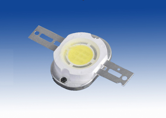
Flyback LED drive GM, because the structure can be used for input voltage higher or lower than the required output voltage. In addition, when the flyback circuit operating in discontinuous inductor current mode, able to maintain a constant LED current, no additional control loop. The circuit described in this application note is based on highly integrated MAX16802 PWM LED driver IC.
Application
* LED track lighting
* Universal LED lighting
Feature
* 10.8V to 24V input voltage range
* Single 3.3V LED power supply, provide 350mA (typical) current (LED configuration structure, designed in accordance with the design steps)
* 29V (typical) anode to the maximum open circuit voltage
* 262kHz switching frequency
*-By-cycle current limit
* On / off control input
* Allows the use of low-frequency PWM signal to adjust the brightness
* You can adjust the circuit to adapt to the various forms of series, parallel LED configuration
Typical Application Circuit
Note: + VLED-VLED and LED lights connections, do not give circuitry.
Component list
Circuit topology
* Open-loop, non-isolated flyback LED drive is very general and easy to use. It has a number of advantages, and very popular. These benefits include:
* The need for an external control loop to adjust the LED current
* Non-continuous inductor current transfer reduces EMI emissions
* Lower switch conduction losses
* Simple circuit design process
LED voltage can be higher or lower than the input voltage
* A wide input voltage range
* Easy access to the PWM dimming signal
The biggest advantage is the cost of the following shortcomings:
* The LED current is limited by component tolerances, for example, the inductor and galvanometer comparator propagation delay
* Non-continuous inductor current mode, so that the topology is more suitable for low power applications
Design steps
The most important parameter is the LED current. The high-brightness LED current is generally a few hundred mA. In order to extend the working life of LED, the current must remain constant; power is essentially a current drive. There are several ways to achieve a simple and low-cost solution: using a dedicated current mode PWM controller IC, for example, while the MAX16802 is. The advantages of the device is:
* A high level of integration – required few external components
* Up to 262kHz switching frequency
* Tiny 8-pin μMAX
* Smaller galvanometer threshold, to reduce losses
* Accurate oscillation frequency, to help reduce the LED current changes
* On-chip voltage feedback amplifier can be used to limit the output open-circuit voltage
Given the LED parameters are:
Step 1: calculate the minimum input voltage, the best approximation of the duty cycle:
Where Rb is the ballast resistor R11 in the application circuit in this application is set to 1. VD is the forward voltage drop of the rectifier diode D1.
The known values in the above equation:
Step 2: Calculate the peak inductor current approximation:
Kf is a critical error coefficient, set at 1.1.
The known values into the above equation to get:

Step 3: Calculate the required inductance approximation, and select the less than and closest to the calculated value of the standard inductance:
Where L is the L1 in the application circuit; f is the switching frequency is equal to of 262kHz.
The known values into the above equation to get:
Below this value, the closest standard value of 10μH.
Step 4: the process of passing through the flyback output power:
The output circuit power dissipation is equal to:
According to the principle of conservation of energy, the two formulas should be equal, you can get a more accurate peak inductor current:
Where L is the actual choice of standard inductance values.
Known values, we can get:
Step 5: Calculate the galvanometer resistance, derived by R9 and R10 in parallel; calculate the voltage detection voltage divider (if needed), consisting of R6 and R7.
The MAX16802 is the current limit threshold of 291mV. Therefore, R9, R10, R6 and R7 to meet the inductor peak current calculated in step 4.
Upon completion of this step, you can get the value of the various components of the application circuit, The circuit provides 12V, 350mA output. Because of the parasitics, the resistance value (R7) need to make proper adjustments to get the desired current.
Step 6: R1 and R2 are optional. They are used to adjust the + VLED to 29V. This is very useful output unexpected open. If the partial pressure of the above components, the output voltage is likely to rise, resulting in damage to the device.
Components C1 and R5 is optional, used to stabilize the voltage feedback loop. For the current application, you can not use these components.
