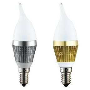
High-power LED lights are increasingly being used in a variety of areas, including automotive lighting, camera phone flash, stage lighting, workplace lighting, landscape lighting, flash, bicycle lights and cars running lights. This article will discuss the various technical problems and distribution switches in LED applications.
At present, the limiting distribution switch is one of the best choice for designers used to drive the LED. This is because the distribution switch operation, and better able to control the distribution system a variety of load. Its function is simple: in the state of the switch is turned on, allowing current to flow to the load, the switch turned off, preventing current flow to the load.

This switch also has a limiting function, that is, when the switch is turned on, the maximum current load is equal to the current limit set by the switch. This limit function is necessary to design a constant current LED driver.
Why designer so need to constant-current LED drive? LED light intensity is constant because the flow through the LED current is constant, even in the case of flow through the LED voltage change will not change. This is necessary for the application of the requirements of a stable light intensity.
When the switch is open, the LED will try to absorb as current as possible, but due to limitations of the switch, only 350mA. Therefore, as long as the switch is open, and switch the input voltage (Vin) within the range of 2.5V to 5.5V, the flow through the LED current can be always maintained in the 350mA.
With current-limiting switch, the LED current limit will be able to be adjusted between 200 mA to 2 A by changing the resistor values in Rset. A limiting value range so wide, you can apply to a variety of high-power LED, and can be used for a variety of applications.
This IC with Cslew pin capacitor between Cslew and Vin to connect through it. Cslew capacitors can be used to extend the opening time of the LED. At the same time, it comes with a built-load discharge transistor (P-channel FET). When the switch is off, the FET will release the output current.
In some applications, the need to gradually open and close the LEDs, so the audience will not be sudden change in light conditions and transient blindness. Figure 3 shows one can arbitrarily set the opening time and closing time of the program.
Here, open the input and Vin are related (Figure 3 display Cslew pin) pin Ilimit issued a 5 V signal to open and close the control.
To calculate the limiting value of the circuit in Figure 3, the required sum of 0.5 kΩ and 0.2 kΩ (3.33 kΩ and 0.212 kΩ resistor in the equivalent resistance), obtained 0.7 kΩ. In this case, the limiting value is 245/0.7 kΩ = 350 mA. In addition, through a 680 μF capacitor values, opening and closing time is set at 300 ms. This time is calculated: 2.2 x R x C = 2.2 x 0.2 kΩ x 680 μF = 300 ms.
MIC2007 can switch to turn on and adjust the current limit after the LED is lit. By changing the current limit, it can dynamically adjust the LED light intensity. Shown in Figure 5, there are four resistors are connected to Ilimit pin.
If 4 of the resistor value, the LED light intensity can have four different levels. Several resistors connected to Ilimit pin, you can get several levels of the LED light intensity.
If the resistor’s value, by using different combinations of resistors to adjust the intensity of LED light. For example, if the resistance value of R, R / 2, the R / 4, the R / 8 and R/16 5 resistors have been used, the combination of R, the R / 2 and R / 4 three resistors LED The light intensity is even lower, while the combination of R / R / 8 R/16 three resistors, LED’s light intensity is higher.
Micrel’s MIC2000 series limiting distribution switch allows a maximum of 2A current flows to load such a large current is sufficient for most of the load in the system. Limiting distribution switches to many designers are using the high power LED load to meet the growing demands of a variety of lighting applications in the market today.

