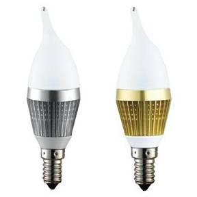
Automotive lighting assembly suppliers are considering the use of LED lights devices with high-intensity discharge (HID) lighting competition. First, the LED device driver circuit complexity of the HID lamp. HID lamps require high voltage ballast circuit starts an arc in the HID lamp, and in the Kai-arc needs to adjust its voltage output to maintain constant power supply HID lamps. From the electromagnetic compatibility (EMC) point of view, these high-voltage circuits are prone to noise, further hampered the technology for use in the automotive sector. Finally, the cost of the LED devices continued to decline, to make this technology more and more attractive for cost-sensitive automotive market.

A typical LED headlamp application requirements to provide more than about 25 watts of power to the LED array. One of the advantages of the LED components is high efficiency, drive electronic components should also improve efficiency, to give full play to the advantages of LED street lights technology. Consider some kind of switching power supply (SMPS) to achieve this goal (see Figure 1). But most of the SMPS design goal is to adjust the voltage rather than current.
For this application, select the buck topology. Limit of the input voltage (VBATT = 9 V min.) And the array of forward voltage drop (2xVF = 8.0 V, VFMAX = 4 V IF = 350 mA) to determine the expectations of a buck topology to meet these requirements, it is reasonable to . The method of driving the LED is switch / voltage stability, and then flows through the LED current adjusted by pulse width modulation. In the path of the LED and switch, you need a current limiting resistor in series in order to avoid too much current flows through the potential damage. This series resistance power consumption can lead to reduced efficiency.
However, SMPS with conducive to the steady flow component. Simplified buck regulator circuit shown in Figure 2.
Simplified schematic of the buck regulator
More careful observation of the energy storage elements in this design can be found some interesting points. Current through the inductor can be seen as both exchanges is also a DC component. Consider the work of SMPS inductor in discontinuous mode (inductor current waveform, see Figure 3). In this application, the DC component is of particular concern. Because the current is the key parameter, and adjust the current to the load is the main objective of this circuit. Should also remember that the exchange of components to minimize the target.
continuous mode flow through the inductor current waveform
In addition, because they do not consider the output voltage, and it changes with the LED devices, and thus does not require the same like a conventional voltage regulator circuit to consider this node regulator task. When the inductor charging and to help provide energy to the LED down lights array, the output capacitor current during this period Traditional regulator, this component will be retained.
