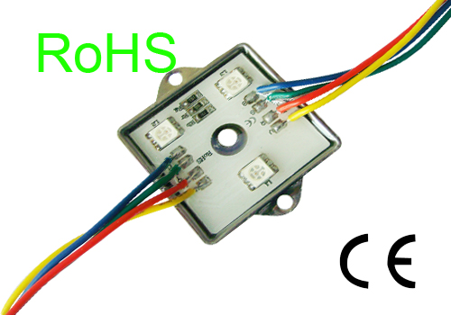
White LED has been widely used in handheld devices such as mobile phones as a color LCD screen backlight and keypad light. Color LED is a good indicator of the situation reported to the user calls and battery charging. The brightness of the LED lights current is proportional to the voltage must be high enough so that they conduction. Now the most popular battery is a lithium battery, the voltage is usually 3.6V or so, but as the battery discharges, the voltage will drop. For these reasons, the LED can not directly use this battery-powered, you also need an adjustable boost converter. Adjustable charge pump solution is very popular, especially in the total output current less than 100mA of simple and low-cost applications.

Different current drive LED
Adjustable output charge pump, such as Catalyst’s CAT3200-5 is one of the ideal LED driver can provide up to 100mA 5V regulator output load current. For LCD backlight white LED current is 20mA, the forward voltage VF of approximately 3.4V. The current through each LED tubes series resistor to set the resistance is also known as ballast resistors (see Figure 1). This structure allows parallel through different current in the LED. Larger resistance value smaller means that the LED current. In Equation 1, the approximate draw of the LED current (ignoring interconnect losses).
adjustable output charge pump applications
Formula 1: VOUT = the VF + (LED current × RS).
, VF is the LED forward voltage, RS is the series resistance.
The stability of the output voltage VOUT 5V, take into account when the forward voltage VF of 3.4V when the LED current is 20mA, RS = (5V-3.4V) / 20mA, or 80 ohms. In this example, three white LED display backlight, two color LED (red and blue) as the indicator. Each color LEDs have different forward voltage characteristics. The red LED forward voltage is very low, 20mA of current when voltage is typically 2.8V. Indicator LED is not used for lighting, so its current is smaller than the backlight LED tube.
the application of the adjustable current charge pump
The CAT3200-5 of the charge pump is one kind of voltage doubler, and only needs a large capacitor as the accumulation of container, the charge transfer from input to output. It is recommended to use a 1μF ceramic capacitor. All external components of the other two 1μF capacitors, were placed in the input and output pins.
Market there are still other LED driver implementations, such as inductor boost or charge pump current control. Inductor boost drive with an inductance to the input voltage is increased to drive several LEDs in series, The advantage is that these LED provide the same current, but this structure is not suitable for the above application examples. Another LED drive current control of the charge pump, by using the on-chip current regulation, a separate LED channels can drive an LED. In this case, the size of the LED current set by external resistors. In a more complex drives, via a digital interface can be programmed into the chip inside to go. The advantage of this structure is no longer needed for ballast resistors. Since all the LED current is the same, so this solution is not suitable for the applications we discuss.
The power supply with a series resistance of the electrical schematic Figure
The most critical issues often appear when the system is powered on. When the enable input pin of the signal from a logic low to logic high conversion, the device turns on and charge a large capacitor. Results in a very short period of time input current increases rapidly, resulting in the so-called “surge” current. Used to describe the advantages of an indicator of the power management chip is how did it perform in the monitoring of the input current. High surge current risks associated with internal rail voltage (VRAIL) instantly drop and affect the system operation. The decline in rail voltage power supply output impedance RS and interconnect impedance RINTER function (see Figure 3).
System rail voltage is calculated as follows: VRAIL = VBAT-IIN × (RSINTER,
Which, VBAT is the battery voltage, IIN is the input current. For example, if the series resistance of the sum of 1.5 (inrush current is 0.5A, then the rail voltage: VRAIL = 3.6V (0.5A × 1.5 ohm) = 2.85V.
VIN 3.3V and the load current of 100mA power on
Such a low voltage can cause a system crash. A way to reduce the inrush current of the battery output is to increase the input capacitance of CIN. As a result, most of the large capacitor charging current provided by the capacitor, CIN can reduce the inrush current. Figure 4 depicts the input capacitance of 1μF and 4.75μF input current and output voltage waveform.
The input current waveform when the linear growth in the output voltage to the rated 5V input current is gradually increased. The initial current spikes because only a very short period of 2μs duration, so no harm, it has little effect on the input voltage.
