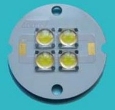
Common substrate types of rigid printed circuit boards (PCB), high thermal conductivity coefficient of aluminum plate, ceramic substrates, soft printed circuit boards, metal composite materials. Low-power LED Lights package with PCB version of the ordinary for the electronics industry to meet the demand, but more than more than 0.5W LED packaging (t5 high bay fixture) are mostly switched to the metal lines and ceramic high heat dissipation substrate, mainly due to the cooling of the substrate LED life The performance has a direct impact on the package substrate is a very important component in the design of high brightness LED products application.

In the process of the general electricity into light, nearly 80% turn to the heat. We rely on the heat sink for cooling. In fact, a lot of heat in so small space does not burn particles, but it makes the light more and more weak, which is commonly referred to as the light fades. Only the heat out fast, the light fades before the smaller.
The thermal expansion and dimensional stability of three of the application advantages of LED Tubes components (t5 high bay fixture) listed below:
1, heat
At present, a lot of double sided, multilayer density, power, heat dissipation is difficult. Conventional PCB substrates such as FR4, CEM3 are poor conductor of heat insulation layer, the heat does not go out. Electronic equipment does not rule out local heating, resulting in the high-temperature failure of electronic components, metal-based printed circuit board can solve this thermal problem.
2, the thermal expansion
Thermal expansion and contraction is the common nature of the material, the different substances CTE (Coefficient of thermal expansion) coefficient of thermal expansion is different. The PCB is resin + reinforced materials (such as fiberglass) + complexes of copper foil. XY axis direction of the board, the PCB coefficient of thermal expansion (CTE) of 13 to 18 PPM / ℃, 80 to 90PPM / ° C in the plate thickness Z-axis direction, the CTE of copper of as 16.8PPM / ℃. Sheet of ceramic chip carrier CTE of as 6PPM / ℃, PCB plated hole wall and connected to the insulated wall in the Z-axis CTE is a big difference, the heat generated can not be immediately removed, thermal expansion and contraction so that the through holes cracking disconnect, such machinery and equipment is not reliable.
SMT (surface mount technology) to make this issue more prominent, the problem must be solved. Surface mount interconnect is achieved through the direct connection of the surface of the solder joint, the CTE of the ceramic chip carrier 6, while the FR4 substrate in the XY CTE of 13 to 18, therefore, mount connector solder joints due to different CTE long (t5 high bay fixture) withstand the stress can lead to fatigue fracture.
3, the dimensional stability
Metal based PCB, apparently size than the insulating material PCB is much more stable. Printed circuit board of aluminum, aluminum sandwich panel, heated from 30 ℃ to 140 to 150 ° C, the dimensional changes of 2.5 to 3.0%. The metal base circuit board with excellent thermal conductivity, good machining performance and strength, good electromagnetic shielding performance, good magnetic performance. Product design follows the semiconductor conduction mechanism, and therefore not only the thermal conductivity of the metal circuit board (metal PCB): aluminum plate, copper substrate has good thermal conductivity, heat dissipation. And the green environmental protection, both to solve the heat problem to solve environmental problems.
